EasyManua.ls Logo

Sony SA-WS500RF Service Manual

Sony SA-WS500RF
51 pages
To Next Page IconTo Next Page
Page #1 background imageLoading...
Page #1 background image
Sony Video & Sound Products Inc.
SERVICE MANUAL
Conditions of Use:
(1) Please use this information only for the purpose of performing repair, maintenance and/or con guration services of the Sony products (hereinafter the “Repair services”) under the ser-
vice agreement entered into with the Sony group company (hereinafter the “Service agreement”). Using this information for any purpose other than the purpose described foregoing is
forbidden.
(2) Only the Authorized Servicer’s of cers, employees or subcontractors (including their of cers and employees) whose duties justify a need-to-know and who have agreed to hold
con dential this information (collectively hereinafter the “Permitted users”) are permitted to access and use this information. To disclose or disseminate to any person other than the
Permitted users is forbidden.
(3) Destroy or erase any and all portion of this information promptly in an irrecoverable and secure fashion after achieving the purpose described in Section (1) above.
(4) Do not copy, replicate, reproduce, alter, translate, transmit, sell, lease, or distribute this information in whole or in part without the prior written permission of the author.
(Notwithstanding foregoing, it is permitted to copy and distribute this information to the Permitted users.)
(5) Please notify immediately any leakage, loss, theft, misappropriation, or other misuse of this information by e-mail to the following address:
somk-gcs-tissnexim-adm@jp.sony.com
(6) In addition to the above, the terms and conditions of the Service agreement shall be applied to using this information.
Revision of Information:
This information may be changed or updated at any time without any prior notice. Please con rm that this information is up-to-date before using it.
Sony CONFIDENTIAL
For Authorized Servicer
9-896-531-02
2018I33-1
©
2018.09
HT-S500RF/S700RF
SA-WS500RF/WS700RF/SS-S500RF/S700RF/SS500RF/SS700RF
Note:
Be sure to keep your PC used for service and
checking of this unit always updated with the
latest version of your anti-virus software.
In case a virus affected unit was found during
service, contact your Service Headquarters.
SYSSET
2018/11/2806:27:54(GMT+09:00)

Table of Contents

Question and Answer IconNeed help?

Do you have a question about the Sony SA-WS500RF and is the answer not in the manual?

Sony SA-WS500RF Specifications

General IconGeneral
BrandSony
ModelSA-WS500RF
CategoryHome Theater System
LanguageEnglish

Summary

Conditions of Use

SPECIFICATIONS

General

Covers general product specifications like power, dimensions, and mass.

Inputs

Lists the available input terminals for audio and data.

Output

Details the output terminals and their configurations.

HDMI section

Specifies the HDMI connector type and details.

USB section

Describes the USB port specifications.

BLUETOOTH section

Outlines Bluetooth connectivity standards and range.

Speaker section

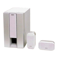
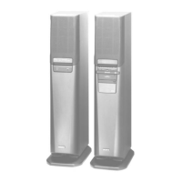
Details the speaker system configuration and type.

Compatible iPhone/iPod models

Copyrights and Trademarks

SECTION 1 SERVICING NOTES

UNLEADED SOLDER

Guidelines for working with unleaded solder and its characteristics.

ADVANCE PREPARATION WHEN CONFIRMING OPERATION

Lists necessary units for confirming system operation before service.

DISCHARGE PROCESSING

Procedures for safely discharging capacitors to prevent electric shock.

ABOUT THE PROTECTION

Explains the system's protection feature and how to address it.

DESTINATION ABBREVIATIONS

Defines abbreviations used for regional model variations.

MODEL IDENTIFICATION

OPERATION CHECK OF THE BLUETOOTH CONNECTION

RESET METHOD

REPAIRING OF THE BAR SPEAKER AND SURROUND SPEAKERS

NOTE OF REPLACING THE ELECTRICAL PARTS ON EACH BOARDS FOR REPAIRING

Specifies which parts can be replaced from the parts list.

SPREADING OF COMPOUND

Instructions on applying thermal compound during component replacement.

SECTION 2 DISASSEMBLY

2-1. DISASSEMBLY FLOW

Outlines the sequence of disassembly steps for the unit.

2-2. CATCHER RUBBER (REAR SIDE), REAR PANEL

Details the removal of rear components like the catcher rubber and rear panel.

2-3. AMP BLOCK, CATCHER RUBBER (FRONT SIDE)

Explains how to remove the front catcher rubber and amplifier block.

2-4. TOP CHASSIS BLOCK, POWER CORD

Covers the removal of the top chassis and power cord assembly.

2-5. BT BOARD

Step-by-step guide for removing the Bluetooth board.

2-6. SPK JACK BOARD

Procedure for detaching the speaker jack board.

2-7. MAIN BOARD

Instructions for removing the main circuit board.

2-8. POWER BOARD

Details the process of removing the power supply board.

2-9. FRONT PANEL BLOCK

Guide to disassembling the front panel assembly.

2-10. FL BOARD, SW PANEL, LED WINDOW W TOUCH

Covers the removal of the FL board, SW panel, and LED window.

2-11. SW UNIT (SUBWOOFER)

Procedure for removing the subwoofer unit.

2-12. SERVICE POSITION

Demonstrates the correct orientation for servicing the unit.

SECTION 3 TEST MODE

SOFTWARE VERSION DISPLAY MODE

How to check software version, destination, and model name.

FACTORY RESET

Procedure to clear settings and Bluetooth pairing history.

BYPASS EQ MODE

Method to disable the equalizer setting.

SECTION 4 TROUBLESHOOTING

1. Starting up (SA-WS500RF/WS700RF)

Troubleshooting steps for unit startup issues.

2. Touch button does not work (SA-WS500RF/WS700RF)

Diagnosing and resolving issues with the touch button functionality.

3. Check the audio output (SA-WS500RF/WS700RF)

SECTION 5 DIAGRAMS

5-1. BLOCK DIAGRAM

High-level overview of the system's functional blocks and connections.

Circuit Boards Location

Illustrates the physical placement of main circuit boards within the unit.

IC Block Diagrams

Detailed block diagrams for specific integrated circuits.

5-2. PRINTED WIRING BOARD - MAIN Board (SA-WS500RF/WS700RF)

Shows the component layout on the MAIN board's component and conductor sides.

5-3. SCHEMATIC DIAGRAM - MAIN Board (1/8) (SA-WS500RF/WS700RF)

Part 1 of the MAIN board schematic, detailing power supply circuits.

5-4. SCHEMATIC DIAGRAM - MAIN Board (2/8) (SA-WS500RF/WS700RF)

Part 2 of the MAIN board schematic, focusing on MCU and related connections.

5-5. SCHEMATIC DIAGRAM - MAIN Board (3/8) (SA-WS500RF/WS700RF)

Part 3 of the MAIN board schematic, covering MTK processor and interface signals.

5-6. SCHEMATIC DIAGRAM - MAIN Board (4/8) (SA-WS500RF/WS700RF)

Part 4 of the MAIN board schematic, detailing audio input and ADC circuits.

5-7. SCHEMATIC DIAGRAM - MAIN Board (5/8) (SA-WS500RF/WS700RF)

Part 5 of the MAIN board schematic, showing HDMI and SPDIF interface circuits.

5-8. SCHEMATIC DIAGRAM - MAIN Board (6/8) (SA-WS500RF/WS700RF)

Part 6 of the MAIN board schematic, illustrating speaker output driver circuitry.

5-9. SCHEMATIC DIAGRAM - MAIN Board (7/8) (SA-WS500RF/WS700RF)

Part 7 of the MAIN board schematic, detailing amplifier power stages.

5-10. SCHEMATIC DIAGRAM - MAIN Board (8/8) (SA-WS500RF/WS700RF)

Part 8 of the MAIN board schematic, showing final power amplifier stages.

5-11. PRINTED WIRING BOARD - SPK JACK Board (SA-WS500RF/WS700RF)

Shows the component layout for the SPK JACK board.

5-12. SCHEMATIC DIAGRAM - SPK JACK Board (SA-WS500RF/WS700RF)

Provides the schematic for the SPK JACK board.

5-21. SCHEMATIC DIAGRAM - POWER Board (SA-WS500RF: LA/WS700RF: BR, LA)

Schematic for the POWER board for LA/BR/LA regional models.

IC Pin Function Description

MAIN BOARD U5 STM32F070RBT6 (MCU)

Details the pin functions for the STM32F070RBT6 microcontroller on the MAIN board.

MAIN BOARD U7 MT8301OXE (DIGITAL AUDIO INTERFACE RECEIVER, DSP)

Details pin functions for the MT8301OXE receiver/DSP on the MAIN board.

MAIN BOARD U15-U18 TAS5614LADDVR Amplifier ICs

Pin functions for the TAS5614LADDVR amplifier ICs on the MAIN board.

MAIN BOARD U9 MTK8301 Processor IC

Pin functions for the MTK8301 processor IC on the MAIN board.

SECTION 6 EXPLODED VIEWS

6-1. SUBWOOFER FRONT SECTION (SA-WS500RF)

Exploded view of the SA-WS500RF subwoofer's front assembly and parts.

6-2. SUBWOOFER AMP SECTION (SA-WS500RF)

Exploded view of the SA-WS500RF subwoofer's amplifier section and components.

6-3. SUBWOOFER FRONT SECTION (SA-WS700RF)

Exploded view of the SA-WS700RF subwoofer's front assembly and parts.

6-4. SUBWOOFER AMP SECTION (SA-WS700RF)

Exploded view of the SA-WS700RF subwoofer's amplifier section and components.

6-5. BAR SPEAKER, SURROUND SPEAKER SECTION (SS-S500RF/SS500RF)

Exploded views of the SS-S500RF bar and surround speaker sections.

6-6. BAR SPEAKER, SURROUND SPEAKER SECTION (SS-S700RF/SS700RF)

Exploded views of the SS-S700RF bar and surround speaker sections.

SECTION 7 ELECTRICAL PARTS LIST

SECTION 8 ACCESSORIES

REVISION HISTORY

Related product manuals