EasyManua.ls Logo

Sony SCD-1/777ES User Manual

Sony SCD-1/777ES
78 pages
To Next Page IconTo Next Page
Page #1 background imageLoading...
Page #1 background image
SERVICE MANUAL
For Technical service
US Model
Canadian Model
AEP Model
SCD-1/777ES
3. SERVICING NOTES ............................................... 3
4. DISASSEMBLY-2 ..................................................... 5
5. TEST MODE.............................................................. 10
6. ELECTRICAL ADJUSTMENTS......................... 12
7. DIAGRAMS
7-1. Notes for Printed Wiring Board and
Schematic Diagram ......................................................... 17
7-2. Printed Wiring Boards – RF/SLD-FG/SLD-MOT
Boards –........................................................................... 18
7-3. Schematic Diagram – RF/SLD-FG/SLD-MOT
Boards –........................................................................... 19
7-4. Printed Wiring Boards – LOAD-CN/LOAD-MOT/
LOAD-SW/STB Boards – .............................................. 20
7-5. Schematic Diagram – LOAD-CN/LOAD-MOT/
LOAD-SW/STB Boards – .............................................. 21
7-6. Printed Wiring Board – MAIN Board
(component side) –.......................................................... 22
7-7. Printed Wiring Board – MAIN Board
(conductor side) – ........................................................... 23
7-8. Schematic Diagram – MAIN Board (1/7) – .................. 24
7-9. Schematic Diagram – MAIN Board (2/7) – .................. 25
7-10. Schematic Diagram – MAIN Board (3/7) – .................. 26
7-11. Schematic Diagram – MAIN Board (4/7) – .................. 27
7-12. Schematic Diagram – MAIN Board (5/7) – .................. 28
7-13. Schematic Diagram – MAIN Board (6/7) – .................. 29
7-14. Schematic Diagram – MAIN Board (7/7) – .................. 30
7-15. Printed Wiring Board – AUDIO Board – ...................... 31
7-16. Schematic Diagram – AUDIO Board (1/2) – ................ 32
7-17. Schematic Diagram – AUDIO Board (2/2) – ................ 33
7-18. Printed Wiring Boards – BAL(SCD-1)/COAX/
OPT/PIN/SW Boards – ................................................... 34
7-19. Schematic Diagram – BAL(SCD-1)/COAX/
OPT/PIN/SW Boards – ................................................... 35
7-20. Printed Wiring Boards – DISPLAY/SW-L/
SW-R Boards –................................................................ 36
7-21. Schematic Diagram – DISPLAY/SW-L/
SW-R Boards –................................................................ 37
7-22. Printed Wiring Boards – AC/POWER Boards – ........... 38
7-23. Schematic Diagram – AC/POWER Boards –................ 39
7-24. IC Pin Function Description ........................................... 43
8. EXPLODED VIEWS ................................................ 50
9. ELECTRICAL PARTS LIST ............................... 59
TABLE OF CONTENTS
Question and Answer IconNeed help?

Do you have a question about the Sony SCD-1/777ES and is the answer not in the manual?

Sony SCD-1/777ES Specifications

General IconGeneral
TypeCD Player
Disc formatsCD, CD-R, CD-RW
Signal-to-Noise Ratio120 dB
Dynamic range100 dB
Digital outputsCoaxial, Optical
Weight26 kg
Frequency Response2 Hz - 20 kHz
Total Harmonic Distortion0.0018%
Analog outputsRCA
Output Voltage2.0V

Summary

Servicing Notes and Model Identification

Optical Pick-up Block Handling

Handling precautions for optical pick-up block and flexible board.

Laser Diode Emission Safety Check

Safety guidelines for checking laser diode emission.

Model Identification

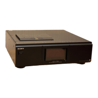
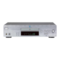
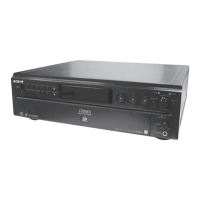
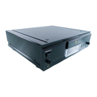
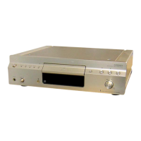
Identifies different models of the product.

Service Position

Details on the physical setup for servicing.

Disassembly Procedures

OP Mechanism Section Disassembly

Disassembly steps for the optical pick-up mechanism.

Main Board Disassembly

Disassembly steps for the main board.

Test Modes

Fluorescent Indicator Tube Test Mode

Test mode to check all segments of the display.

Electrical Adjustments

Adjustment Notes and Traverse Check

General notes and procedure for traverse waveform check.

S Curve and RF Level Checks

Procedures for S curve and RF level checks.

CLV Jitter and Pick-up Height Adjustment

Procedures for CLV jitter check and pick-up height adjustment.

Overall Adjustment Procedure

Procedure for performing overall system adjustments.

Diagrams and Schematics

PWB and Schematic Diagram Notes

Notes on interpreting PWB and schematic diagrams.

RF, SLD-FG, SLD-MOT Boards Diagrams

PWB layouts and schematic for RF, SLD-FG, SLD-MOT boards.

LOAD, STB Boards Diagrams

PWB layouts and schematic for LOAD and STB boards.

Main Board PWB and Schematic Diagrams

PWB layouts and schematic diagrams for the MAIN board.

Main Board Schematic Diagrams (cont.)

Schematic diagrams for the MAIN board (parts 2/7 to 7/7).

Audio Board Diagrams

PWB layouts and schematic diagrams for the AUDIO board.

BAL, COAX, OPT, PIN, SW Boards Diagrams

PWB layouts and schematic diagrams for BAL, COAX, OPT, PIN, SW boards.

Display, SW-L, SW-R Boards Diagrams

PWB layouts and schematic diagrams for DISPLAY, SW-L, SW-R boards.

AC/POWER Boards Diagrams

PWB layouts and schematic diagrams for AC/POWER boards.

Waveform Diagrams

Waveforms from RF, MAIN, AUDIO, and DISPLAY boards.

IC Block Diagrams

Block diagrams for IC101 and IC302 on the AUDIO board.

IC Pin Function Descriptions

Pin descriptions for key ICs on MAIN board.

Exploded Views

General Assembly Views (SCD-1/777ES)

Exploded views of general assembly for SCD-1 and SCD-777ES.

Loading and Front Panel Views

Exploded views of loading and front panel sections.

Main, Chassis, and OP Mechanism Views

Exploded views of main, chassis, and OP mechanism sections.

Electrical Parts Lists

AC, Audio, Bal, Coax Parts List

Electrical parts list for AC, Audio, Bal, and Coax boards.

RF, SLD-FG, SLD-MOT, STB Parts List

Electrical parts list for RF, SLD-FG, SLD-MOT, STB boards.

SW, SW-L, SW-R Parts List

Electrical parts list for SW, SW-L, SW-R boards.

Main Board Parts List

Electrical parts list for the MAIN board.

Main Board Parts List (cont.)

Electrical parts list for the MAIN board (cont.).

Main, Opt, Pin Parts List

Electrical parts list for Main, Opt, and Pin boards.

Power, RF Parts List

Electrical parts list for Power and RF boards.

Related product manuals