Do you have a question about the Sony SCD-XE597 and is the answer not in the manual?
Details the technical specifications of the SCD-XE597 and lists similar models.
Provides instructions for safe handling of the optical pick-up and laser diode emission checks.
Offers guidance on replacing chip components and repairing flexible circuit boards.
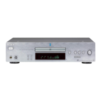
Explains how to open the disc tray when the power is off and identifies the unit model.
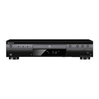
Details and describes the functions of the controls on the front panel of the player.
Provides a detailed explanation of each button on the remote commander.
Outlines the overall disassembly sequence and the procedure for removing the unit cover.
Details the steps for disassembling the main board and the loading panel.
Describes the disassembly process for the front panel, key board, and display board.
Provides instructions for disassembling the CD mechanism deck and the base unit.
Details the disassembly of the RF board, pick-up unit, belt, and motor assembly.
Contains notes for interpreting diagrams, waveform examples, and circuit board locations.
Illustrates the block diagram for the optical pick-up unit.
Shows the printed wiring board layouts for the RF section (Side A and Side B).
Presents the schematic diagram for the RF board.
Includes printed wiring board layouts for the main and loading boards.
The first part of the main board schematic diagram.
The second part of the main board schematic diagram.
The third part of the main board schematic diagram.
The fourth part of the main board schematic diagram.
Printed wiring board layouts for the display, LED, and key boards.
Schematic diagrams for the display, power switch, and LED boards.
Illustrates the block diagrams for integrated circuits on the main board.
An exploded view detailing the components of the main section of the unit.
An exploded view showing the assembly of the front panel.
An exploded view detailing the parts of the CD mechanism deck.
An exploded view illustrating the components of the base unit (DVBU50).
Includes notes on standardization, part stocking, and categories like Capacitors, Resistors, Semiconductors.
Lists components for the display, key, LED, and loading boards.
A comprehensive list of capacitors used on the main board.
Lists connectors, diodes, ICs, and resistors for the main board.
Summarizes parts for Main, Power SW, PT boards and lists composition circuit blocks.
Lists components for the RF board and includes a list of accessories.
Introduces the test mode and electrical adjustment procedures covered in the supplement.
Details how to enter, operate, and use commands within the test mode.
Covers ROM version checks, optical sensitivity checks, and shipping mode settings.
Records the versions, dates, and descriptions of revisions made to the service manual.
| Type | CD Player |
|---|---|
| Disc Compatibility | CD, CD-R, CD-RW |
| Frequency Response | 2 Hz - 20 kHz |
| Total Harmonic Distortion | 0.002% |
| Dynamic Range | 100 dB |
| Output Voltage | 2.0 V |
| Digital Output | Coaxial |
| Power Consumption | 15 W |
| Channels | 2 Channels |
| Dimensions (W x H x D) | 430 x 95 x 290 mm (17 x 3 3/4 x 11 1/2 inches) |