Do you have a question about the Sony SCD-XB940 and is the answer not in the manual?
Notes on safely handling the optical pick-up block to prevent electrostatic damage.
Guidelines for safely checking the laser diode emission from the optical pick-up.
Methods to manually open the disc tray when the power is off.
Details for identifying the AEP and UK models by part numbers.
Troubleshooting steps for the "E01" display error.
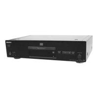
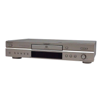
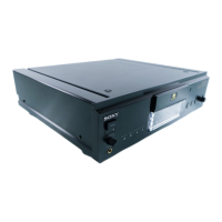
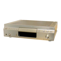
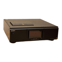
Overview of controls and connectors on the front and rear panels.
Description of buttons and features on the remote commander.
Information on playable disc formats and incompatible disc types.
Procedure for disassembling the outer cover and front panel sections.
Steps for removing the audio/main board and mechanism deck.
Specific instructions for removing the disc tray.
General notes and symbols used in diagrams and PWB layouts.
Printed wiring board and schematic diagrams for the TK board.
PWB layouts and schematic diagrams for the MAIN board (multiple parts).
Printed wiring board and schematic diagrams for the AUDIO board.
PWB layouts and schematic diagrams for HP, Loading, Display, Power, and AC SW/Transformer boards.
Illustrations of key signal waveforms for various boards.
Block diagrams illustrating the internal structure of key ICs.
Exploded view diagram showing the components of the cover section.
Exploded view diagram showing the components of the front panel section.
Exploded view diagram showing the components of the chassis section.
Exploded view diagram showing the components of the mechanism deck.
Comprehensive list of electronic components used in the unit.
How to enter, exit, and navigate the test mode menus.
Details on various self-diagnosis tests for system components.
Procedures for auto-adjustments, manual operations, and disc checks.
Descriptions of other test modes like Version Info and RF Jitter.
Tables listing mechanism and DSP error codes and their meanings.
| Channels | 2 |
|---|---|
| Total Harmonic Distortion | 0.002% |
| Dynamic Range | 100 dB |
| Output Level | 2.0 V |
| Digital Output | Coaxial |
| Analog Output | RCA |
| Disc Formats | CD, CD-R, CD-RW |
| Frequency Response | 2 Hz - 20 kHz |
| Dimensions | 430 x 115 x 290 mm |
| Type | Super Audio CD Player |
| Digital-to-Analog Converter | 1-bit D/A converter |