EasyManua.ls Logo

Sony SCD-XB770 Service Manual

Sony SCD-XB770
88 pages
To Next Page IconTo Next Page
Page #1 background imageLoading...
Page #1 background image
SERVICE MANUAL
SUPER AUDIO CD PLAYER
AEP Model
UK Model
SCD-XB770
Ver 1.1 2001.07
SPECIFICATIONS
Model Name Using Similar Mechanism NEW
CD Mechanism Type CDM66B-DVBU6
Base Unit Name DVBU-6
Optical Pick-up Name KHM-230AAA
9-873-846-12 Sony Corporation
2001G0500-1 Home Audio Company
C 2001.7 Shinagawa Tec Service Manual Production Group

Other manuals for Sony SCD-XB770

Question and Answer IconNeed help?

Do you have a question about the Sony SCD-XB770 and is the answer not in the manual?

Sony SCD-XB770 Specifications

General IconGeneral
TypeCD Player
Dynamic Range100 dB
Digital OutputsCoaxial
Disc FormatsCD, CD-R, CD-RW
OutputsAnalog (RCA)
Dimensions (W x H x D)430 x 98 x 285 mm

Summary

SPECIFICATIONS

General Specifications

Covers laser type, power, dimensions, and mass.

Laser Specifications

Details the laser type, wavelength, and emission duration.

Power & Dimensions

Specifies voltage, frequency, power consumption, dimensions, and mass.

Supplied Accessories

Lists items included with the player, like cords and batteries.

SERVICING NOTES

Optical Pick-up Handling Precautions

Warns about ESD and handling flexible boards for optical pick-up.

Laser Diode Emission Check Procedure

Provides guidelines for checking laser diode emission safely.

Optical Pick-up Lens Cleaning

Recommends using an air blower for cleaning the pick-up lens.

Tray Opening Without Power Instructions

Instructions for manually opening the disc tray when power is off.

Service Procedures

Display Board Service Position

Details how to position the display board for service.

Trans Board Installation Procedure

Explains the correct procedure for installing the trans board.

Power-On Operation Sequences

CD Power-On Sequence

Describes the power-on sequence when a CD is loaded.

SACD (Single Layer) Power-On Sequence

Outlines the power-on sequence for single-layer SACDs.

SACD (Dual Layer) Power-On Sequence

Details the power-on sequence for dual-layer SACDs.

GENERAL INFORMATION

Front Panel Controls Overview

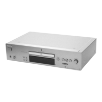
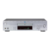
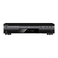
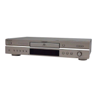
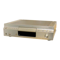
Identifies and describes front panel controls and indicators.

Rear Panel Connections Overview

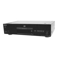
Identifies and describes rear panel connectors and outputs.

Remote Control Functions

Remote Control Button Descriptions

Explains the function of each button on the remote control.

COMPATIBLE DISC TYPES

Disc Layer Configuration Types

Explains different SACD and CD layer configurations.

SACD Channel Configuration Types

Details channel configurations for SACD discs.

Incompatible Disc Types List

Lists discs that cannot be played by this player.

DISASSEMBLY PROCEDURE

Disassembly Flowchart

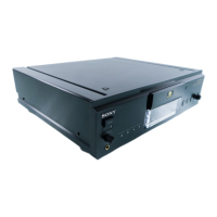
Outlines the sequence for disassembling the set.

Cover Removal Steps

Details the procedure for removing the unit's cover.

Component Disassembly

Front Panel Section Disassembly Steps

Describes the steps for disassembling the front panel.

Audio and Main Board Removal Steps

Explains the removal of audio and main circuit boards.

Mechanism Deck Disassembly Steps

Details the disassembly of the mechanism deck.

Base Unit Disassembly

Base Unit Removal Steps

Describes the disassembly of the base unit.

TEST MODE PROCEDURES

Required Test Discs and Their Purpose

Lists required discs for various test modes.

Entering and Navigating Test Mode Menu

Explains how to enter and navigate the test mode menu.

Overview of Test Mode Commands

Lists available test mode commands and their descriptions.

Test Mode Command Categories

FOCUS Command Functions

Details commands related to focus adjustments.

OFFSET Command Functions

Covers commands for adjusting PI, FE, and TE signal offsets.

TRACKING Command Functions

Lists commands related to tracking servo adjustments.

SEARCH Command Functions

Describes commands for track search functions.

DISC DETECT Command Functions

Commands for checking disc type.

Advanced Test Mode Commands

TOOLS Command Functions

Commands for aging, parameter reading, and adjustments.

QA Command Functions

Lists commands for set checks and aging.

Manual Servo Operation Guide

Guides on applying servo manually in test mode.

Set Check Mode Operations

SET CHECK Menu Structure Explained

Outlines the structure of the SET CHECK menu.

MANUAL CHK Detailed Procedures

Explains how to perform individual checks within MANUAL CHK.

IC and Display Tube Diagnostics

IC and Display Tube Check Procedure

Details the procedure for checking IC communication and display.

IC Communication Error Causes

Lists error displays and their typical causes during IC checks.

Common Causes for IC Communication Failures

Lists common issues affecting IC communication and voltage.

AUTO CHECK PROCEDURES

Auto Check Mode Setup Method

Explains how to set up and initiate automatic checks.

CD and SACD (SL) Disc Check Steps

Details the check procedure for CD and SACD (SL) discs.

Auto Check Items and Descriptions

Lists various items checked during auto-scan.

Auto Check Specified Values

SACD Disc Check Specified Values

Provides specified values for SACD disc checks.

Auto Check Specified Values (cont.)

CD Disc Check Specified Values

Lists specified values for CD disc checks.

Hexadecimal Data Display Interpretation

Explains how to interpret hexadecimal data displays.

Specific Disc Operation Checks

SACD (DL) Disc Operation Check Procedure

Details the procedure for checking dual-layer SACD operation.

SACD (DL) Disc Check Specified Values

Lists specified values for DL disc operation checks.

HYBRID Disc Operation Check Procedure

Explains how to check hybrid disc layer switching stability.

HYBRID Disc Check Specified Values

Lists specified values for hybrid disc operation checks.

AGING AND SHIPPING MODES

AGING MODE Setup and Error Handling

Details how to set up and start the aging process and handle errors.

SHIPPING MODE Procedure and Settings

Explains how to set the unit to shipping mode for initialization.

Error Display and System Errors

Error Display Items and Descriptions

Explains the meaning of various display items and error names.

Error List and Main Causes

Lists errors, their descriptions, and main causes.

System Errors Not Saved in Set

Details system errors that are not saved in the set.

WAVEFORMS CHECK PROCEDURES

BU Electrical Adjustment Mode Overview

Explains the mode for checking S curve, traverse, and RF waveforms.

S Curve Waveform Check Details

Details connection and checking for S curve waveforms.

Traverse Waveform Check Details

Explains connection and checking for traverse waveforms.

Waveform Check Details

RF Level Waveform Check

Details connection and checking for RF level waveforms.

CLV Jitter Waveform Check

Explains connection and checking for CLV jitter waveforms.

Waveform Connection Locations

Pinpoints locations for oscilloscope connections on the main board.

SECTION 5 DIAGRAMS

5-1. BLOCK DIAGRAM - RF/SERVO Section

Shows the block diagram for the RF/Servo section.

SECTION 5 DIAGRAMS (cont.)

5-2. BLOCK DIAGRAM - SERVO Section

Displays the block diagram for the Servo section.

SECTION 5 DIAGRAMS (cont.)

5-3. BLOCK DIAGRAM - MAIN Section

Presents the block diagram for the Main section.

SECTION 5 DIAGRAMS (cont.)

5-4. BLOCK DIAGRAM - AUDIO Section

Illustrates the block diagram for the Audio section.

SECTION 5 DIAGRAMS (cont.)

5-5. BLOCK DIAGRAM - DISPLAY/KEY/POWER SUPPLY Section

Shows the block diagram for display, key, and power supply.

SECTION 5 DIAGRAMS (cont.)

5-6. NOTES ON BOARDS AND DIAGRAMS

Provides notes on interpreting diagrams and board layouts.

Circuit Board Locations Overview

Shows the physical locations of various circuit boards.

SECTION 5 DIAGRAMS (cont.)

5-7. SCHEMATIC DIAGRAM - RF Board

Contains the schematic diagram for the RF board.

SECTION 5 DIAGRAMS (cont.)

5-8. PRINTED WIRING BOARDS - RF/LOADING Boards

Shows the printed wiring boards for RF and Loading sections.

SECTION 5 DIAGRAMS (cont.)

5-9. PRINTED WIRING BOARD - MAIN Board (Component Side)

Details the component side layout of the main board.

SECTION 5 DIAGRAMS (cont.)

5-10. PRINTED WIRING BOARD - MAIN Board (Conductor Side)

Shows the conductor side layout of the main board.

SECTION 5 DIAGRAMS (cont.)

5-11. SCHEMATIC DIAGRAM - MAIN (1/5)/LOADING Boards

Provides the schematic for the main and loading boards.

SECTION 5 DIAGRAMS (cont.)

5-12. SCHEMATIC DIAGRAM - MAIN Board (2/5)

Contains the schematic diagram for the main board, part 2.

SECTION 5 DIAGRAMS (cont.)

5-13. SCHEMATIC DIAGRAM - MAIN Board (3/5)

Presents the schematic diagram for the main board, part 3.

SECTION 5 DIAGRAMS (cont.)

5-14. SCHEMATIC DIAGRAM - MAIN Board (4/5)

Shows the schematic diagram for the main board, part 4.

SECTION 5 DIAGRAMS (cont.)

5-15. SCHEMATIC DIAGRAM - MAIN Board (5/5)

Illustrates the schematic diagram for the main board, part 5.

SECTION 5 DIAGRAMS (cont.)

5-16. SCHEMATIC DIAGRAM - AUDIO/HP Boards

Details the schematic diagrams for audio and headphone boards.

SECTION 5 DIAGRAMS (cont.)

5-17. PRINTED WIRING BOARDS - AUDIO Board (Component Side)

Shows the component side of the audio board's printed wiring.

SECTION 5 DIAGRAMS (cont.)

5-18. PRINTED WIRING BOARDS - AUDIO (Conductor Side)/HP Boards

Displays conductor side of audio and HP boards' wiring.

SECTION 5 DIAGRAMS (cont.)

5-19. PRINTED WIRING BOARDS - DISPLAY/KEY Boards

Shows the printed wiring for display and key boards.

SECTION 5 DIAGRAMS (cont.)

5-20. SCHEMATIC DIAGRAM - DISPLAY/KEY Boards

Contains the schematic diagrams for display and key boards.

SECTION 5 DIAGRAMS (cont.)

5-21. PRINTED WIRING BOARDS - POWER/TRANS Boards

Illustrates the printed wiring for power and trans boards.

SECTION 5 DIAGRAMS (cont.)

5-22. SCHEMATIC DIAGRAM - POWER/TRANS Boards

Details the schematic diagrams for power and trans boards.

WAVEFORM ANALYSIS

RF Board Sample Waveforms

Displays sample waveforms from the RF board.

Main Board Sample Waveforms

Shows sample waveforms from the main board.

Waveform Analysis (cont.)

IC Component Sample Waveforms

Presents sample waveforms from various ICs.

Waveform Analysis (cont.)

Audio Board Sample Waveforms

Displays sample waveforms from the audio board.

Display Board Sample Waveforms

Shows sample waveforms from the display board.

IC BLOCK DIAGRAMS

RF Board IC Block Diagrams

Provides block diagrams for ICs on the RF board.

IC Block Diagrams (cont.)

Main Board IC Block Diagrams

Shows block diagrams for ICs on the main board.

IC Block Diagrams (cont.)

Main Board IC Block Diagrams (cont.)

Continues block diagrams for main board ICs.

IC Block Diagrams (cont.)

Audio Board IC Block Diagrams

Illustrates block diagrams for ICs on the audio board.

IC PIN FUNCTION DESCRIPTIONS

IC509 CXD3068Q Pin Functions

Details pin functions for IC509 (Digital Signal Processor).

IC Pin Function Descriptions (cont.)

IC509 CXD3068Q Pin Functions (cont.)

Continues pin functions for IC509.

IC Pin Function Descriptions (cont.)

IC701 CXD1882R-1 (SACD Decoder) Pin Functions

Details pin functions for IC701 (SACD Decoder).

IC Pin Function Descriptions (cont.)

IC701 Pin Functions (cont.)

Continues pin functions for IC701.

IC Pin Function Descriptions (cont.)

IC509 Pin Functions (cont.)

Continues pin functions for IC509.

IC Pin Function Descriptions (cont.)

IC509 Pin Functions (cont.)

Continues pin functions for IC509.

IC Pin Function Descriptions (cont.)

IC801 CXD2752R (DSD Decoder) Pin Functions

Details pin functions for IC801 (DSD Decoder).

IC Pin Function Descriptions (cont.)

IC801 Pin Functions (cont.)

Continues pin functions for IC801.

IC Pin Function Descriptions (cont.)

IC801 Pin Functions (cont.)

Continues pin functions for IC801.

IC Pin Function Descriptions (cont.)

IC803 CXD9647R (DSD Processor) Pin Functions

Details pin functions for IC803 (DSD Processor).

IC Pin Function Descriptions (cont.)

IC803 Pin Functions (cont.)

Continues pin functions for IC803.

IC Pin Function Descriptions (cont.)

IC901 CXP973F064-203R (CPU) Pin Functions

Details pin functions for IC901 (CPU).

IC Pin Function Descriptions (cont.)

IC901 Pin Functions (cont.)

Continues pin functions for IC901.

IC Pin Function Descriptions (cont.)

IC902 CXD1095BR (I/O Expander) Pin Functions

Details pin functions for IC902 (I/O Expander).

IC Pin Function Descriptions (cont.)

IC902 Pin Functions (cont.)

Continues pin functions for IC902.

EXPLODED VIEWS SECTION

Cover Section Exploded View

Provides an exploded view of the unit's cover and related parts.

Exploded Views Section (cont.)

Front Panel Section Exploded View

Shows an exploded view of the front panel and its components.

Exploded Views Section (cont.)

Chassis Section Exploded View

Details the chassis components in an exploded view.

Power Board and Transformer Exploded Views

Shows exploded views of power board and transformers.

Exploded Views Section (cont.)

Mechanism Deck Section Exploded View

Exploded view of the mechanism deck (CDM66B-DVBU6).

Exploded Views Section (cont.)

Base Unit Section Exploded View

Exploded view of the base unit (DVBU-6).

ELECTRICAL PARTS LIST

AC SW and Audio Board Parts List

Lists electrical parts for AC SW and Audio sections.

Electrical Parts List (cont.)

Audio Board Components List

Lists audio board components including ICs, connectors, and transistors.

Audio Board Resistor and Capacitor Lists

Lists resistors and capacitors for the audio board.

Electrical Parts List (cont.)

Main Board Resistor List

Lists various resistors for the main board.

Main Board Capacitor List

Lists various capacitors for the main board.

Electrical Parts List (cont.)

Connector, LED, IC, Transistor, Resistor Lists

Lists connectors, LEDs, ICs, transistors, and resistors for various boards.

Capacitor Lists for Display and RF Boards

Lists various capacitors for display and RF boards.

Electrical Parts List (cont.)

Main Board Capacitor List (cont.)

Lists additional capacitors for the main board.

Electrical Parts List (cont.)

Main Board Capacitor List (cont.)

Lists further capacitors for the main board.

RF Board Connector, Diode, and Ferrite Beads List

Lists RF board connectors, diodes, and ferrite beads.

Electrical Parts List (cont.)

RF Board ICs, Coils, and Transistors List

Lists ICs, coils, and transistors for the RF board.

RF Board Resistor List

Lists various resistors for the RF board.

Electrical Parts List (cont.)

RF Board Resistor List (cont.)

Lists additional resistors for the RF board.

Electrical Parts List (cont.)

RF Board Resistor List (cont.)

Continues listing resistors for the RF board.

Electrical Parts List (cont.)

Main and Power Board Component Lists

Lists components for main and power boards, including heat sinks and screws.

Electrical Parts List (cont.)

RF Board Diodes, ICs, and Ferrite Beads List

Lists RF board diodes, ICs, and ferrite beads.

Electrical Parts List (cont.)

Trans Board Component Lists

Lists transistors, resistors, and capacitors for the trans board.

REVISION HISTORY

Manual Revision Details

Lists revisions made to the manual with dates and descriptions.

Related product manuals