Do you have a question about the Sony SCD-CE595 and is the answer not in the manual?
Details playback frequency range, frequency response, dynamic range, and distortion for SACD.
Lists frequency response, dynamic range, and distortion for CD playback.
Specifies output connector types, levels, and load impedance for audio signals.
Covers general specs like laser type, power requirements, dimensions, mass, and accessories.
Precautions for handling optical pick-up and laser diode emission checks.
Guidelines for replacing chip components and repairing flexible circuit boards.
Warning about safety-critical components and the necessity of using specified Sony parts.
Procedures for performing safety checks and AC leakage tests on exposed metal parts.
Information on model identification and the procedure to manually open the disc tray.
Detailed explanation of front panel buttons, indicators, and their functions.
Explains the functions of each button on the remote commander for controlling the player.
Instructions for entering DIAG MODE and operating the test mode.
Lists and explains the commands available in the test mode for various functions.
Lists commands for automatic electrical adjustments, applicable for specific system versions.
Explains diagram conventions and shows the physical location of circuit boards.
Illustrates critical waveforms for RF, Main, and Display boards.
Illustrates the overall system architecture and interconnections of major components.
Depicts the printed wiring board layout for the RF section, showing component placement.
Illustrates the printed wiring board layout for the Main section, detailing component placement.
Printed wiring board layouts for Display, Power SW, LED, and Key boards.
Printed wiring board layouts for the MD-94 and SE-130 sections.
Detailed schematic diagram for the RF section, showing component connections and signals.
First part of the detailed schematic for the Main section, showing component interconnections.
Second part of the Main section schematic, detailing circuit connections and signal paths.
Third part of the Main section schematic, illustrating circuit details and component relationships.
Final part of the Main section schematic, showing remaining circuit details and connections.
Detailed schematic diagrams for Display, Power SW, LED, and Key boards.
Detailed schematic diagrams for the MD-94 and SE-130 sections.
Block diagram and pin function description for the system controller IC705.
Continuation of pin function descriptions for IC705, covering remaining pins.
Exploded diagram of the main section, showing assembly of mechanical and electronic parts.
Exploded diagram of the front panel, illustrating its components and assembly.
Exploded diagram of the chassis section, detailing its mechanical parts and their arrangement.
First part of the exploded view for the CD mechanism section, showing its components.
Second part of the exploded view for the CD mechanism section, detailing further components.
Comprehensive list of electrical components including capacitors, connectors, transistors, resistors, and ICs with part numbers.
Continues the parts list with components for Key, LED boards, capacitors, connectors, diodes, and resistors.
Lists specific capacitors and connectors for the Main board.
Details diodes, jacks, transistors, resistors, and ICs for the Main board.
Continues the parts list with resistors, chip networks, vibrator, connectors, and switches for Main and MD-94 boards.
Lists electrical components for Power SW, PT, and RF boards, including capacitors, connectors, ICs, coils, transistors, and resistors.
Details components for the SE-130 board and lists accessories like manuals and commander.
Supplement covering test modes and electrical adjustment procedures for the device.
Instructions for entering DIAG MODE and operating the test mode.
Lists and explains the commands available in the test mode for various functions.
Lists commands for automatic electrical adjustments, applicable for specific system versions.
General description of adjustments and procedure for checking ROM version.
Procedures for U-CON check and optical sensitivity calibration.
Steps to set the unit to shipping mode after EEPROM replacement.
Records revisions made to the service manual, including dates and descriptions of changes.
| Frequency range | 2 - 100000 Hz |
|---|---|
| CD Text | Yes |
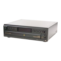
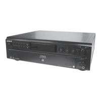
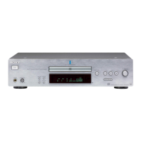
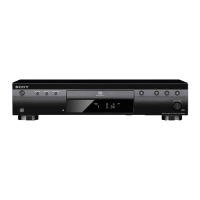
| Device type | HiFi CD player |
| Cassette deck | No |
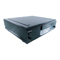
| Product color | Black |
| Media types supported | CD-R. CD-RW |
| FM band range | 87.5 - 108 MHz |
| I/O ports | Digital Output (only CD) for MD / DAT: coaxial/optical, Gold Plated Line Out, Headphone, Headphone variable, SACD Multichannel Out, Super Audio CD Out, Super Audio CD Stereo Out |
| Dimensions (WxDxH) | 430 x 290 x 115 mm |
| Power requirements | 230 V, 50/60 Hz |
| Power consumption (standby) | 0 W |
| Power consumption (typical) | 25 W |
| Weight | 5600 g |
|---|