Sony Corporation
SERVICE MANUAL
Revision History
LEVEL 3
Check the SERVICE NOTE (LEVEL 2) before the service.
983473211.pdf
2013C08-1
© 2013.03
Published by Sony Techno Create Corporation
INTERCHANGEABLE LENS DIGITAL CAMERA
The components identified
by mark 0 or dotted line with
mark 0 are critical for safety.
Replace only with part number
specified.
Les composants identifiés par
une marque 0 sont critiques pour
la sécurité.
Ne les remplacer que par une
pièce portant le numéro spécifié.
US Model
Canadian Model
AEP Model
UK Model
Russian Model
E Model
Australian Model
Chinese Model
Korea Model
9-834-732-11
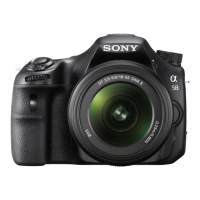
SLT-A58K/A58M/A58Y
Photo: SLT-A58 (Main body)
SLT-A58K/A58M/A58Y_L3
Ver. 1.0 2013.03
[About the service of this model]
SLT-A58K/A58M/A58Y are commodity that packed the Interchangeable Lens Digital Camera and Interchangeable Lenses.
Refer to each following service manual the Interchangeable Lens kit, when you repair.
Model Lens Service Manual of Lens
SLT-A58K SAL1855-2 (DT 18-55mm F3.5-5.6 SAM II) 9-834-733-[]
SLT-A58M SAL18135 (DT 18-135mm F3.5-5.6 SAM) 9-834-677-[]
SLT-A58Y SAL1855-2 (DT 18-55mm F3.5-5.6 SAM II) 9-834-733-[]
SAL55200-2 (DT 55-200mm F4-5.6 SAM) 9-852-692-[]
Ver. Date History Contents
S.M. Rev.
issued
1.0 2013.03 Official Release — —