EasyManua.ls Logo

Sony SLV-E730UX User Manual

Sony SLV-E730UX
79 pages
To Next Page IconTo Next Page
Page #1 background imageLoading...
Page #1 background image
MICROFILM
SERVICE MANUAL
AEP Model
SLV-E630AE
French Model
SLV-E730B/735B
East European Model
SLV-E580EE/E780EE
Middle European Model
SLV-E580EG/E780EG/E780EN
North European Model
SLV-E730NC/E735NC
Irish Model
SLV-E730EX
Spanish Model
SLV-E630NP/E730NP
UK Model
SLV-E730UX
German Model
SLV-E727VC/E730VC/E730VP/E735VC
RMT-V220B/V221D/V223/V223A/V223B/V224/V224C
VIDEO CASSETTE RECORDER
SLV-E580EE/E580EG/E630AE/E630NP/E727VC/E730B/E730EX/E730NC/E730NP/
E730UX/E730VC/E730VP/E735B/E735NC/E735VC/E780EE/E780EG/E780EN
G
Refer to the SERVICE MANUAL of VHS MECHANICAL
ADJUSTMENTS VI for MECHANICAL ADJUSTMENTS.
(9-921-647-11)
* The abbreviations of E580, E630, E727, E730, E735, E780 con-
tained in this service manual are indicated when these models
are common to all their corresponding models as given below.
Photo: SLV-E780
S MECHANISM
E580EE
E580EG
E630AE
E630NP
E727VC
E580 E630 E727
Abbreviated
model name
All model
names
SLV-
E730B
E730EX
E730NC
E730NP
E730UX
E730VC
E730VP
E730
E735B
E735NC
E735VC
E735
E780EE
E780EG
E780EN
E780

Table of Contents

Question and Answer IconNeed help?

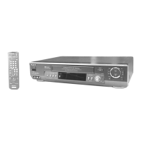
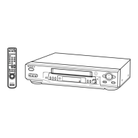
Do you have a question about the Sony SLV-E730UX and is the answer not in the manual?

Sony SLV-E730UX Specifications

General IconGeneral
BrandSony
ModelSLV-E730UX
CategoryVCR
LanguageEnglish

Summary

SECTION 1 GENERAL

Erste Schritte

Initial setup and remote control operation.

Steuern anderer Fernsehgeräte mit der Fernbedienung

Using the remote for various TV brands.

SECTION 2 DISASSEMBLY

2-1. UPPER CASE REMOVAL

Procedure to remove the upper case.

2-2. REAR PANEL REMOVAL

Procedure to remove the rear panel.

2-3. FRONT PANEL SECTION REMOVAL

Procedure to remove the front panel section.

2-4. FR-127, DM-72 BOARD REMOVAL

Procedure to remove FR-127, DM-72 boards.

SECTION 3 BLOCK DIAGRAMS

3-1. OVERALL BLOCK DIAGRAM

Overview of the system's functional blocks.

3-2. VIDEO BLOCK DIAGRAM

Diagram illustrating the video signal path.

3-3. SERVO/SYSTEM CONTROL BLOCK DIAGRAM

Diagram of servo and system control circuits.

3-4. I/O, C+ BLOCK DIAGRAM

Diagram for input/output and C+ signals.

3-5. AUDIO BLOCK DIAGRAM

Diagram illustrating the audio signal path.

3-6. TUNER BLOCK DIAGRAM

Diagram of the tuner circuit.

SECTION 4 PRINTED WIRING BOARDS AND SCHEMATIC DIAGRAMS

4-1. FRAME SCHEMATIC DIAGRAM

Overall schematic of the unit's frame.

4-2. PRINTED WIRING BOARDS AND SCHEMATIC DIAGRAMS

Location and diagrams of printed wiring boards.

SECTION 5 INTERFACE, IC PIN FUNCTION DESCRIPTION

SECTION 6 ERROR CODES

Table 6-1. Error Codes

List of error codes and their meanings.

Table 6-2. Mode Codes in Case of Error

List of mode codes displayed during errors.

SECTION 7 ADJUSTMENTS

7-1. MECHANICAL ADJUSTMENTS

Procedures for mechanical adjustments.

7-2. ELECTRICAL ADJUSTMENTS

Procedures for electrical adjustments.

2-1. PRE-ADJUSTMENT PREPARATIONS

Necessary items and indications for electrical adjustment.

2-2. POWER SUPPLY ADJUSTMENT

Steps for adjusting power supply voltages.

2-3. SERVO SYSTEM Adjustment

Procedures for servo system adjustments.

2-4. VIDEO SYSTEM ADJUSTMENT

Procedures for video system adjustments.

2-5. AUDIO SYSTEM ADJUSTMENTS

Procedures for audio system adjustments.

SECTION 8 REPAIR PARTS LIST

8-1. EXPLODED VIEWS

Visual breakdown of parts for replacement.

8-1-1. FRONT PANEL AND CABINET ASSEMBLIES

Exploded view of front panel and cabinet parts.

8-1-2. CHASSIS ASSEMBLY

Exploded view of the chassis assembly.

8-1-3. MECHANISM CHASSIS ASSEMBLY (1)

Exploded view of the mechanism chassis part 1.

8-1-4. MECHANISM CHASSIS ASSEMBLY (2)

Exploded view of the mechanism chassis part 2.

8-1-5. MECHANISM CHASSIS ASSEMBLY (3)

Exploded view of the mechanism chassis part 3.

8-2. ELECTRICAL PARTS LIST

List of electrical components and their part numbers.

Related product manuals