Do you have a question about the Sony SLV-SE100 and is the answer not in the manual?
Lists numerical error codes and their corresponding descriptions.
Covers initial setup steps like unpacking and connecting the VCR.
Explains fundamental VCR functions like playing and recording tapes.
Provides a comprehensive overview of the VCR's system architecture.
Illustrates the signal flow and processing within the VCR's video section.
Details the servo and system control functions and their interconnections.
Details IC162 pin functions for the video and record/playback blocks.
Explains IC162 pin functions for servo control and peripheral circuits.
Details IC162 pin functions for the mechanism control block.
Lists pin functions for the servo/system control microprocessor (IC162).
Lists required equipment and connection setup for electrical adjustments.
Details set-up, alignment tapes, and specific voltage checks.
Covers RF switching position and other servo system checks.
| Type | VCR |
|---|---|
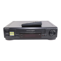
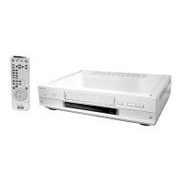
| Brand | Sony |
| Model | SLV-SE100 |
| Video Format | VHS |
| Audio System | Mono |
| Number of Heads | 2 |
| Hi-Fi Stereo | No |
| Remote Control | Yes |
| On-Screen Display | Yes |
| Power Requirements | AC 120V, 60Hz |
| Recording Speed | SP, LP |
| Playback Speed | SP, LP |
| Connections | Composite video, Audio |
| Inputs | RF, Composite video, Audio |
| Outputs | Composite video, Audio |