EasyManua.ls Logo

Sony SLV-SE620 User Manual

Sony SLV-SE620
96 pages
To Next Page IconTo Next Page
Page #1 background imageLoading...
Page #1 background image
VDE
vaes
SLV-SE220/SE420/SE620/SE720/
SE727/SE820/SX720/SX72
RMT-V405/V405A/V406/V406A/V406B/V407A/V407B/V407C
SERVICE
MANUAL
AEP
Model
SLV-SE220/SE620/SE720/SE727/
eas
SE820/SX720/SX727
UK
Model
SLV-SE220G/SE720G/SE820
Russian
Model
SLV-SE420K/SE620N/SE720N/
VHS
SE820N/SX720N
o
oO
wo
loelFa
SHOWVIEW’
[ud-4=
Photo
:
SLV-SE620D
(engi
(for
UK
model)
RMT-V406
TS-10
MECHANISM
|
Refer
to
the
SERVICE
MANUAL
of
VHS
MECHANI-
CAL
ADJUSTMENT
MANUAL
VII
for
MECHANICAL
ADJUSTMENTS.
(9-921-790-11)
The
abbreviations
of
SLV-SE220/SE420/SE620/SE720/SE727/SE820/SX720/SX727
contained
in
this
service
manual
are
indicated
when
these
models
are
common
to
all
their
corresponding
models
as
given
below.
Abbreviated
models
name
|SE220__|SE420__|SE620
_|SE720__|SE727_|SE820
_|$X720
AEP
models
SLV-
SE220B
|SE620B
|SE720B
|SE727E
|SE820B
|Sx720D
|$x727D
SE220D
SE620D_|
SE720D
SE820D
|SX720E
SE2201
SE620E
|
SE720E
SE820E
SE7201
UK
models
SLV-
SE220G
-
-
_|SE720G
-
_|SE820G
ae
“fk
Russian
models
SLV-
-
__|SE420K
|SE620N
|
SE720N
-
_|SE820N
|Sx720N
|
-
The
SLV-SE220D/SE620D/SE720D/SX720D/SX727D/SE820D
model
and
SLV-SE420K/SE620N/SE720N/SX720N/SE820N
model
that
have
destination
of
Germany,
Hungary
and
Austria
are
repaired
only
at
the
centralized
service
centers.
Send
these
model
to
the
centralized
service
centers
for
repair.
SPECIFICATIONS
System
LP:
PAL/MESECAM*
Rewind
time
Channel
coverage
11.70
mm/s
Approx.
|
min.
(with
E180
tape)
e
(recording/playback)
ee)
NTSC
16.67
mm/s
Inputs
and
outputs
se
Sane
f
69
(playback
only)
LINE-1
(EURO
AV)
Ra
eau
EP:
NTSC
11.12
mm/s
21-pin
CE
Se
ens
(playback
only)
Video
input:
pin
20
a)
ee
ice
*MESECAM:
for
B
model
Audio
input:
pins
2
and
6
UHF
channels
21-69
Maximum
recording/playback
time
Video
output:
pin
19
issues
10
hrs.
in
LP
mode
(with
E300
tape)
Audho
aut
putapine
Lands
75-ohm
asymmetrical
aerial
socket
2
SGeinied
onan
pase
Tape
speed
ee
VIDEO
CASSETTE
RECORDER
(recording/playback)
NTSC
33.35
mm/s
(playback
only)
SONY.

Table of Contents

Question and Answer IconNeed help?

Do you have a question about the Sony SLV-SE620 and is the answer not in the manual?

Sony SLV-SE620 Specifications

General IconGeneral
BrandSony
ModelSLV-SE620
CategoryVCR
LanguageEnglish

Summary

IMPORTANT SERVICE GUIDE

MODE SWITCH (PROGRAM SWITCH) ASSEMBLY POINT

Details the alignment process for the mode switch assembly on the main PCB.

HOW TO EJECT THE CASSETTE TAPE

Provides instructions for ejecting a cassette when the unit is unresponsive.

1. General

Step 1: Unpacking

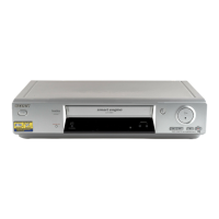
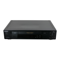
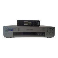
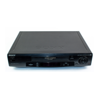
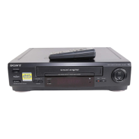
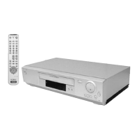
Covers the initial process of taking the VCR out of its packaging and checking contents.

Step 2: Setting up the remote commander

Explains how to insert batteries and set up the remote commander for VCR and TV operation.

Step 3: Connecting the VCR

Details various methods for connecting the VCR to a TV using Scart or aerial cables.

Step 4: Auto Set Up Function

Guides users through the automated setup process for language, channels, and clock.

Step 5: Selecting the TV system

Instructs on choosing the correct TV system for the user's region for optimal performance.

Setting the clock

Explains how to set the VCR's time and date for timer functions and Auto Clock Set.

Selecting a language

Details how to change the on-screen display language from the initial setup.

Presetting channels

Describes manual channel tuning and programming when Auto Set Up is insufficient.

Programme Position Management

Covers changing programme positions and disabling unwanted channels for user convenience.

Changing the station names

Explains how to manually assign names to TV channels for easier identification.

Setting the Canal Plus decoder

Guides on connecting and setting up a Canal Plus decoder for viewing/recording.

Basic Operations

Playing a tape

Instructions for inserting a tape and initiating playback, including additional tasks.

Recording TV programmes

Covers basic recording procedures and methods for different timer types.

Playing/searching at various speeds

Details how to use shuttle ring and other controls for variable speed playback.

Using the shuttle ring

Explains the operation of the shuttle ring for normal and jog mode playback.

Setting the recording duration time

Allows users to set an automatic stop time for recordings.

Timer Settings Management

Covers checking, changing, or cancelling programmed timer settings for recordings.

Stereo and Bilingual Recording

Explains how to record stereo and bilingual audio from broadcasts.

NICAM System Features

Describes the VCR's capability to receive and record NICAM stereo and bilingual audio.

Searching using the index function

Details how to locate recordings using automatically generated index signals.

Editing

Connecting to External Devices

Provides guidance on connecting the VCR to other VCRs or stereo systems.

Basic editing functions

Covers fundamental editing operations like basic editing and audio dubbing.

Audio dubbing

Explains how to record new audio over an existing tape's audio track.

Additional Information

Troubleshooting

Offers solutions for common operational problems encountered with the VCR.

Power Issues

Addresses problems related to the VCR's power supply and standby mode.

Clock and Timer Problems

Provides solutions for issues concerning the VCR's clock and timer functions.

Playback and Recording Issues

Covers troubleshooting for common picture and sound problems during playback and recording.

Canal Plus and Other Issues

Addresses specific problems related to Canal Plus, remote control, and general operational faults.

2. Disassembly

Mono Models Disassembly

Details the disassembly steps for mono VCR models, covering major components.

Hi-Fi Models Disassembly

Outlines the disassembly procedures specific to the Hi-Fi VCR models.

4. Schematic Diagrams

Block Identification of Main PCB

Identifies functional blocks and their locations on the main printed circuit board.

Power Supply Schematics

Presents schematic diagrams for the VCR's power supply units (SMPS and Power Drive).

Control and Servo Schematics

Provides schematic diagrams for the system control and servo sections of the VCR.

Audio/Video and Hi-Fi Schematics

Details schematic diagrams for the audio/video processing and Hi-Fi audio sections.

Signal Processing Schematics

Includes schematics for TM-Block, OSD/VPS/PDC, SECAM, and A2/NICAM signal processing.

Input/Output and Sub-circuit Schematics

Covers schematics for input/output jacks, sub-circuits, waveform, and voltage tables.

5. Alignment and Adjustment

Reference Points for Adjustment

Identifies key reference points and test points for VCR alignment procedures.

Mechanical Adjustment Procedures

Details specific mechanical adjustments like ACE Head Position and Head Switching Point.

NVRAM Option Setting

Guides on setting NVRAM options, critical after replacing the microcomputer or memory.

6. Repair Parts List

Exploded Views for Parts Identification

Provides exploded diagrams and part numbers for VCR components.

Electrical Parts List

Lists electrical components, their part numbers, and specifications for repair.

Related product manuals