– 2 –
Specifications ........................................................................... 1
1. GENERAL
Location and Function of Controls .................................... 2
2. DISASSEMBLY
2-1. “Cabinet ASSY, Front”, “Cabinet ASSY, Rear” ......... 3
2-2. Main Board ................................................................. 3
2-3. LCD201 ...................................................................... 4
2-4. Microcomputer Board................................................. 4
3. ADJUSTMENTS .......................................................... 5
4. DIAGRAMS
4-1. Explanation of IC Terminals....................................... 6
4-2. Block Diagrams .......................................................... 7
4-3. Printed Wiring Boards .............................................. 10
4-4. Schematic Diagram................................................... 13
5. EXPLODED VIEW ..................................................... 17
6. ELECTRICAL PARTS LIST .................................... 18
Flexible Circuit Board Repairing
• Keep the temperature of the soldering iron around 270°C during
repairing.
• Do not touch the soldering iron on the same conductor of the
circuit board (within 3 times).
• Be careful not to apply force on the conductor when soldering or
unsoldering.
Notes on chip component replacement
• Never reuse a disconnected chip component.
• Notice that the minus side of a tantalum capacitor may be dam-
aged by heat.
TABLE OF CONTENTS
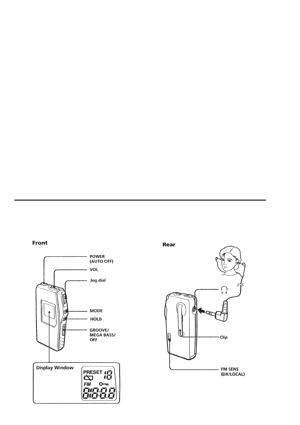
SECTION 1
GENERAL
LOCATION AND FUNCTION OF CONTROLS