EasyManua.ls Logo

Sony SS-CCP1 User Manual

Sony SS-CCP1
46 pages
To Next Page IconTo Next Page
Page #1 background imageLoading...
Page #1 background image
CMT-CP1
US Model
Canadian Model
AEP Model
UK Model
E Model
Australian Model
SERVICE MANUAL
MICROFILM
Sony Corporation
Home A&V Products Company
MICRO Hi-Fi COMPONENT SYSTEM
99B001689-1
Printed in Japan ©1999.2
Published by Quality Assurance Dept.
(Shinagawa)
CMT-CP1 is composed of following models.
As for the service manual, it is issued for each
component model, then, please refer to it.
CMT-CP1
AMPLIFIER/CD PLAYER/
TAPE DECK/TUNER
HCD-CP1
SPEAKER SYSTEM SS-CCP1
•Abbreviation
AED : North European
CND : Canadian
HK : Hong Kong
MY : Malaysia
SP : Singapore
TH : Thai
1-418-299-11 COMMANDER, STANDARD (RM-SCP1)
1-501-374-11 ANTENNA (LOOP) (AM/MW)
1-501-659-61 ANTENNA (FM) (US, CND)
1-754-060-11 ANTENNA (FM) (EXCEPT US, CND)
3-865-909-11 MANUAL, INSTRUCTION (ENGLISH) (EXCEPT AED)
3-865-909-21 MANUAL, INSTRUCTION (FRENCH, SPANISH) (AEP, MY, SP, TH)
3-865-909-31 MANUAL, INSTRUCTION (DUTCH, GERMAN) (AEP)
3-865-909-41 MANUAL, INSTRUCTION (ITALIAN, PORTUGUESE) (AEP)
3-865-909-51 MANUAL, INSTRUCTION (DANISH, FINNISH, SWEDISH) (AED)
3-865-909-61 MANUAL, INSTRUCTION (POLISH) (AED)
3-865-909-71 MANUAL, INSTRUCTION (CHINESE) (MY, SP, HK)
3-865-909-81 MANUAL, INSTRUCTION (FRENCH) (US, CND)
3-865-909-91 MANUAL, INSTRUCTION (ENGLISH, THAI) (TH)
4-991-151-01 COVER, BATTERY (FOR RM-SCP1)
Part No. Description
PARTS LIST(ACCESSORIES & PACKING MATERIALS)
COMPONENT MODEL NAME FOR CMT-CP1
9-928-808-11
Question and Answer IconNeed help?

Do you have a question about the Sony SS-CCP1 and is the answer not in the manual?

Sony SS-CCP1 Specifications

General IconGeneral
BrandSony
ModelSS-CCP1
CategoryStereo System
LanguageEnglish

Summary

SERVICING NOTES

NOTES ON HANDLING THE OPTICAL PICK-UP BLOCK OR BASE UNIT

Safety precautions for handling the optical pick-up block and base unit.

NOTES ON LASER DIODE EMISSION CHECK

Guidelines for safely checking the laser diode emission from the optical pick-up.

SAFETY CHECK-OUT

Procedures to follow after service to ensure the unit's safety before releasing it.

LEAKAGE TEST

Detailed instructions for performing AC leakage tests on exposed metal parts.

GENERAL

LOCATION OF CONTROLS

Identification and description of front and rear panel controls and indicators.

DISASSEMBLY

COVER (UPPER)

Procedure for removing the upper cover of the unit.

TAPE MECHANISM DECK

Steps for disassembling the tape mechanism deck.

FRONT PAENL SECTION

Instructions for disassembling and installing the front panel section.

CD MECHANISM DECK

Steps for disassembling the CD mechanism deck.

SERVICE MODE

Liquid Crystal Display All Lit Check Mode

Procedure to activate the LCD to display all segments for testing.

CD Aging Mode

Mode for operation check of the CD section, including aging sequence.

Tape Deck Aging Mode

Mode for operation check of the tape deck section, including aging sequence.

ELECTRICAL CONFIRMATIONS AND ADJUSTMENTS

Record/Playback Head Azimuth Adjustment

Step-by-step guide for adjusting the record/playback head azimuth.

Playback level Confirmation and Adjustment

Procedure to confirm and adjust playback levels using test tapes.

REC Level Confirmation and Adjustment

Procedure to confirm and adjust recording levels using test signals.

DIAGRAMS

6-1. BLOCK DIAGRAM - TAPE Section -

Block diagram illustrating the signal path and components of the tape section.

6-2. BLOCK DIAGRAM - MAIN Section -

Block diagram showing the main section's signal flow and interconnections.

6-4. NOTE FOR PRINTED WIRING BOARDS AND SCHEMATIC DIAGARAMS

Notes on interpreting printed wiring boards and schematic diagrams, including symbols and abbreviations.

6-6. SCHEMATIC DIAGRAM – MAIN Section (1/4) –

First part of the schematic diagram for the main section.

6-10. PRINTED WIRING BOARDS – PANEL/CD LOADING Section –

Printed wiring board layouts for the panel and CD loading sections.

6-11. PRINTED WIRING BOARDS – CONTROL Section –

Printed wiring board layout for the control section.

6-15. IC PIN FUNCTION DESCRIPTION

Detailed pin descriptions for the main ICs used in the system.

EXPLODED VIEWS

(1) COVER, TAPE MECHANISM DECK SECTION

Exploded view and parts list for the tape mechanism deck cover.

(2) FRONT PANEL SECTION

Exploded view and parts list for the front panel section.

(3) CHASSIS SECTION

Exploded view and parts list for the chassis section.

(4) CD MECHANISM DECK SECTION (KSL-2130CCP/K1N)

Exploded view and parts list for the CD mechanism deck.

ELECTRICAL PARTS LIST

SEMICONDUCTORS

List of semiconductor components used in the unit.

HARDWARE LIST

List of hardware components such as screws used in the assembly.

SS-CCP1 SERVICE MANUAL

SPECIFICATIONS

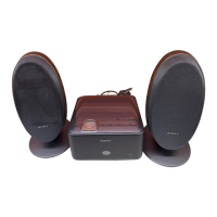
Technical specifications for the SS-CCP1 speaker system.

EXPLODED VIEW AND PARTS LIST

L-CH

Exploded view and parts list for the left channel speaker assembly.

Related product manuals