SERVICE MANUAL
Sony Corporation
Audio Business Group
Published by Sony Techno Create Corporation
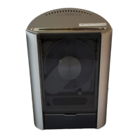
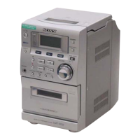
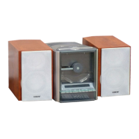
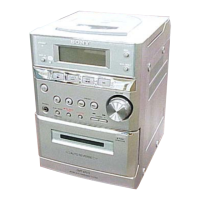
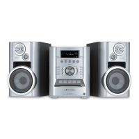
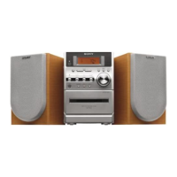
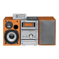
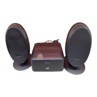
NAS-E35HD/SS-CE35HD
SPECIFICATIONS
9-889-128-01
2008E05-1
©
2008.05
AEP Model
UK Model
E Model
Australian Model
Ver. 1.0 2008.05
CD Section
Model Name Using Similar Drive NEW
Optical Pick-up Block Name KSM215DHAP
HD Section
Model Name Using Similar Drive NEW
Hard Disc Drive Name HDD/SG-NIGHTHAWK-S (80GB)
• SS-CE35HD is the speaker system of
NAS-E35HD.
NAS-E35HD
HDD AUDIO SYSTEM
SS-CE35HD
SPEAKER SYSTEM
European model:
DIN power output (rated):
24 + 24 W (8 Ω at 1 kHz, DIN)
Continuous RMS power output
(reference):
30 + 30 W (8 Ω at 1 kHz, 10 % THD)
Music Power output (reference):
30 + 30 W (8 Ω at 1 kHz, 10 % THD)
Other models:
DIN power output (rated):
24 + 24 W (8 Ω at 1 kHz, DIN)
Continuous RMS power output
(reference):
30 + 30 W (8 Ω at 1 kHz, 10 % THD)
HDD Jukebox section
Capacity:
80 GB*
* A portion of the memory is used
for system management functions.
Actual available memory is approx.
72 GB.
Recording system:
MP3
Maximum recording time (measured
with MP3 128 kbps):
About 1,300 h
Maximum number of tracks:
20,000
Maximum number of albums:
2,000
CD player section
System:
Compact disc and digital audio
system
Laser Diode Properties:
Emission duration: continuous
Laser Output*: Less than 44.6 μw
*
at a distance of 200 mm from the
objective lens surface on the Optical
Pick-up Block with 7 mm aperture.
Frequency response:
20 Hz - 20 kHz
USB section
Supported bit rate
MP3 (MPEG-1 Audio Layer3):
32 - 320 kbps, VBR
WMA:
48 - 192 kbps, VBR
AAC:
48 - 320 kbps
Sampling frequencies
MP3 (MPEG-1 Audio Layer3):
32/44.1/48 kHz
WMA:
44.1 kHz
AAC:
44.1 kHz
– Continued on next page –
Trademarks, etc.
•
“GIGA JUKE” and its logo are trademarks of Sony
Corporation.
•
Title Updater is a trademark of Sony Corporation.
•
“WALKMAN”,
and are
registered trademarks of Sony Corporation.
•
MICROVAULT is a trademark of Sony Corporation.
•
MPEG Layer-3 audio coding technology and patents
•
Media are trademarks or registered trademarks of
countries.
•
such technology outside of this product is prohibited
•
BuiltwithLinterDatabase.
Copyright © 2006-2007, Brycen Corp., Ltd.
Copyright © 1990-2003, Relex, Inc., All rights reserved.
•
Music recognition technology and related data are
provided by Gracenote®. Gracenote is the industry
standard in music recognition technology and related
content delivery. For more information, please visit
www.gracenote.com.
CD and music-related data from Gracenote, Inc.,
service may practice one or more of the following U.S.
Patents: #5,987,525; #6,061,680; #6,154,773, #6,161,132,
#6,230,192, #6,230,207, #6,240,459, #6,330,593, and
other patents issued or pending. Some services supplied
under license from Open Globe, Inc. for U.S. Patent:
#6,304,523.
Gracenote and CDDB are registered trademarks of
the “Powered by Gracenote” logo are trademarks of
Gracenote.
Gracenote® End User License
Agreement
Gracenote, Inc. of Emeryville, California (“Gracenote”).
including name, artist, track, and title information
(“Gracenote Data”) from online servers or embedded
databases (collectively, “Gracenote Servers”) and to
perform other functions. You may use Gracenote Data
only by means of the intended End-User functions of this
application or device.
You agree that you will use Gracenote Data, the Gracenote
non-commercial use only. You agree not to assign, copy,
Gracenote Data to any third party. YOU AGREE NOT
TO USE OR EXPLOIT GRACENOTE DATA, THE
GRACENOTE SOFTWARE, OR GRACENOTE SERVERS,
EXCEPT AS EXPRESSLY PERMITTED HEREIN.
You agree that your non-exclusive license to use the
Servers will terminate if you violate these restrictions.
If your license terminates, you agree to cease any and
and Gracenote Servers. Gracenote reserves all rights
Gracenote Servers, including all ownership rights. Under
no circumstances will Gracenote become liable for any
payment to you for any information that you provide. You
agree that Gracenote, Inc. may enforce its rights under this
Agreement against you directly in its own name.
service to count queries without knowing anything about
who you are. For more information, see the web page for
the Gracenote Privacy Policy for the Gracenote service.
Data are licensed to you “AS IS.” Gracenote makes
no representations or warranties, express or implied,
regarding the accuracy of any Gracenote Data from in
the Gracenote Servers. Gracenote reserves the right to
delete data from the Gracenote Servers or to change data
Gracenote Servers are error-free or that functioning
uninterrupted. Gracenote is not obligated to provide you
with new enhanced or additional data types or categories
that Gracenote may provide in the future and is free to
discontinue its services at any time.
GRACENOTE DISCLAIMS ALL WARRANTIES
EXPRESS OR IMPLIED, INCLUDING, BUT
NOT LIMITED TO, IMPLIED WARRANTIES OF
MERCHANTABILITY, FITNESS FOR A PARTICULAR
PURPOSE, TITLE, AND NON-INFRINGEMENT.
GRACENOTE DOES NOT WARRANT THE RESULTS
THAT WILL BE OBTAINED BY YOUR USE OF THE
GRACENOTE SOFTWARE OR ANY GRACENOTE
SERVER. IN NO CASE WILL GRACENOTE BE LIABLE
FOR ANY CONSEQUENTIAL OR INCIDENTAL
DAMAGES OR FOR ANY LOST PROFITS OR LOST
REVENUES.
names and product names indicated in
this manual are generally the trademarks or registered
trademarks of the manufacturer.
™ and ® marks are omitted in this manual.