EasyManua.ls Logo

Sony SS-CN225 User Manual

Sony SS-CN225
12 pages
To Next Page IconTo Next Page
Page #1 background imageLoading...
Page #1 background image
SERVICE MANUAL
SS-V225 (Front and rear speakers)
Speaker system Full range, magnetically
shielded
Speaker units 5 × 9 cm, cone type
Enclosure type Bass reflex
Rated impedance 8 ohms
Power handling capacity
Maximum input power: 100 watts
Sensitivity level 86 dB (1 W, 1 m)
Frequency range 90 Hz - 20,000 Hz
Dimensions (w/h/d) Approx. 70 × 151 ×
126 mm, including front
grille
Mass Approx. 550 g each
SS-CN225 (Center speaker)
Speaker system Full range × 2,
magnetically shielded
Speaker units 5 × 9 cm, cone type
Enclosure type Bass reflex
Rated impedance 8 ohms
Power handling capacity
Maximum input power: 120 watts
Sensitivity level 88 dB (1 W, 1 m)
Frequency range 90 Hz - 20,000 Hz
Dimensions (w/h/d) Approx. 301 × 70 ×
126 mm, including front
grille
Mass Approx. 1.1 kg
SA-WMS225 (subwoofer)
Speaker system Active subwoofer,
magnetically shielded
Speaker unit Woofer: 16 cm, cone type
Enclosure type Advanced SAW type
Amplifire section
Continuous RMS power output
50 W(8 ohms, 20 - 150 Hz,
0.8% THD)
Reproduction frequency range
28 Hz - 200 Hz
High frequency cut-off frequency
200 Hz
Inputs
LINE IN (input pin jack)
SPEAKER IN (input terminals)
Outputs
LINE OUT (output pin jack)
SPEAKER OUT (output terminals)
General
Power requirements 220 - 230 V AC, 50/60 Hz
Power consumptions 50 W
Dimensions (w/h/d) Approx. 205 × 385 × 385
mm, including front grille
Mass Approx. 10.5 kg
Supplied accessories
Foot pads (20)
Monaural connecting cord (1 phono to 1 phono) (1)
Speaker connecting cords, 10 m (2)
Speaker connecting cords, 3.5 m (3)
Speaker connecting cords, 2.5 m (2)
Design and specifications are subject to change without
notice.
MICRO SATELLITE SYSTEM
AEP Model
UK Model
Ver 1.0 2001.02
9-929-575-11 Sony Corporation
2001B0500-1 Audio Entertainment Group
C 2001.2 General Engineering Dept.
SPECIFICATIONS
SA-VE225/WMS225/
SS-CN225/V225
SA-VE225 consists of the following models respectively.
SA-VE225
Active Subwoofer SA-WMS225
Center Speaker SS-CN225
Front and Rear Speakers SS-V225
SAFETY-RELATED COMPONENT WARNING!!
COMPONENTS IDENTIFIED BY MARK 0 OR DOTTED
LINE WITH MARK 0 ON THE SCHEMATIC DIAGRAMS
AND IN THE PARTS LIST ARE CRITICAL TO SAFE
OPERATION. REPLACE THESE COMPONENTS WITH
SONY PARTS WHOSE PART NUMBERS APPEAR AS
SHOWN IN THIS MANUAL OR IN SUPPLEMENTS PUB-
LISHED BY SONY.
SA-WMS225
SS-V225
SS-CN225
Question and Answer IconNeed help?

Do you have a question about the Sony SS-CN225 and is the answer not in the manual?

Sony SS-CN225 Specifications

General IconGeneral
TypeCenter Channel Speaker
ManufacturerSony
Impedance6 ohms
Power Handling (Max)120 W
Sensitivity88 dB
Tweeter Size1 inch
Speaker Type2-way

Summary

Specifications

SS-V225 Front and Rear Speakers Specifications

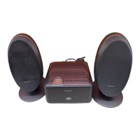
Detailed specifications for the SS-V225 front and rear speaker units.

SS-CN225 Center Speaker Specifications

Detailed specifications for the SS-CN225 center speaker unit.

SA-WMS225 Subwoofer Specifications

Detailed specifications for the SA-WMS225 subwoofer unit.

System Inputs, Outputs, and General Specifications

Details on system inputs, outputs, power requirements, and general dimensions.

Supplied Accessories List

List of accessories included with the system.

Safety-Related Component Warning

Warning regarding critical safety components and replacement procedures.

Diagrams and Notes

Notes for Printed Wiring Boards and Schematic Diagrams

Explanations of symbols and conventions used in wiring boards and schematics.

Circuit Boards Location

Power IC Board Location

Location of the power IC board within the unit.

Power Switch Board Location

Location of the power switch board within the unit.

LED Board Location

Location of the LED board within the unit.

Control Board Location

Location of the control board within the unit.

IC Block Diagrams

Main Board IC Block Diagram

Block diagram illustrating the ICs and functions on the main board.

Power IC Board IC Block Diagram

Block diagram illustrating the ICs and functions on the power IC board.

Printed Wiring Boards (SA-WMS225)

Control Board Layout and Components

Layout of the control board showing component placement and reference numbers.

Power IC Board Layout and Components

Layout of the power IC board showing component placement and reference numbers.

LED Board Layout and Components

Layout of the LED board showing component placement and reference numbers.

Power Switch Board Layout and Components

Layout of the power switch board showing component placement and reference numbers.

Main Board Layout and Components

Layout of the main board showing component placement and reference numbers.

Schematic Diagrams (SA-WMS225)

Main Board Schematic Diagram

Detailed schematic for the main board circuitry.

Control Board Schematic Diagram

Detailed schematic for the control board circuitry.

Power IC Board Schematic Diagram

Detailed schematic for the power IC board circuitry.

LED Board Schematic Diagram

Detailed schematic for the LED board circuitry.

Power Switch Board Schematic Diagram

Detailed schematic for the power switch board circuitry.

Exploded Views

Front Panel Exploded View (SA-WMS225)

Exploded view of the front panel assembly for the SA-WMS225.

Rear Panel Exploded View (SA-WMS225)

Exploded view of the rear panel assembly for the SA-WMS225.

SS-CN225 Exploded View

SS-CN225 Front Panel Assembly

Exploded view showing the front panel parts for the SS-CN225.

SS-CN225 Speaker Cabinet Assembly

Exploded view showing the cabinet parts for the SS-CN225.

SS-CN225 Speaker Terminal

Exploded view showing the speaker terminal parts for the SS-CN225.

SS-CN225 Speaker Units

Exploded view showing the speaker drivers for the SS-CN225.

SS-V225 Exploded View

SS-V225 Front Panel Assembly

Exploded view showing the front panel parts for the SS-V225.

SS-V225 Speaker Cabinet Assembly

Exploded view showing the cabinet parts for the SS-V225.

SS-V225 Speaker Terminal

Exploded view showing the speaker terminal parts for the SS-V225.

SS-V225 Speaker Unit

Exploded view showing the speaker driver for the SS-V225.

SECTION 3 Electrical Parts List

Capacitors, Resistors, and Switches

Lists of capacitors, resistors, variable resistors, and switches.

Integrated Circuits (ICs) and LEDs

Lists of integrated circuits and LEDs used in the system.

Component Lists for Main and Power IC Boards

Connectors, Diodes, Fuses, and Jacks

Lists of connectors, diodes, fuses, and jacks for system connectivity.

ICs, Transistors, Relays, and Transformers

Lists of ICs, transistors, relays, and power transformers.

Resistors and Terminals

Lists of resistors and speaker terminals.

Additional Component Lists and Accessories

Power Switch Components and Miscellaneous

Lists of power switch components, miscellaneous items, and hardware.

Accessories and Packing Materials

Lists of included accessories, packing materials, and manuals.

Revision History

Initial Release (Ver. 1.0)

Details of the initial release of the service manual.

Related product manuals