EasyManua.ls Logo

Sony SS-CHP7 User Manual

Sony SS-CHP7
72 pages
To Next Page IconTo Next Page
Page #1 background imageLoading...
Page #1 background image
CMT-HP7
US Model
Canadian Model
AEP Model
UK Model
E Model
Australian Model
SERVICE MANUAL
MICRO HI-FI COMPONENT SYSTEM
Sony Corporation
Home Audio Company
Published by Sony Engineering Corporation
9-877-348-01
2003F16-1
© 2003.06
CMT-HP7 is composed of following models.
As for the service manual, it is issued for each component
model, then, please refer to them.
SPECIFICATIONS
Ver 1.0 2003. 06
COMPONENT MODEL NAME
COMPACT DISK DECK
RECEIVER SYSTEM
SPEAKER SYSTEM
PARTS LIST
Part No. Description Remark
ACCESSORIES
************
1-477-716-11 COMMANDER, STANDARD(RM-SRG440)
1-501-374-72 ANTENNA, LOOP (AM)
1-754-243-11 ANTENNA (FM)(US, CND)
1-793-184-22 CONNECTOR (F TYPE ADAPTOR)(FM)
(AEP, UK, RU, E2, E3, KR, TW, TH, MX, AUS)
4-228-953-01 COVER, BATTERY (FOR RM-SRG440)
4-246-667-11 MANUAL, INSTRUCTION (ENGLISH)
(US, CND, AEP, UK, RU, E2, E3, TW, AUS)
4-246-667-21 MANUAL, INSTRUCTION (FRENCH)(CND)
4-246-667-31 MANUAL, INSTRUCTION (FRENCH, SPANISH)
(AEP, E2, E3, MX)
4-246-667-41 MANUAL, INSTRUCTION (GERMAN, DUTCH, ITALIAN)(AEP)
4-246-667-51 MANUAL, INSTRUCTION (SWIDISH, POLISH)(AEP)
4-246-667-61 MANUAL, INSTRUCTION (TRADITIONAL CHINESE)(E3, TW)
4-246-667-71 MANUAL, INSTRUCTION (KOREAN)(KR)
4-246-667-81 MANUAL, INSTRUCTION (RUSSIAN)(RU)
4-247-352-11 MANUAL, INSTRUCTION (ENGLISH, THAI)(TH)
4-972-322-01 FOOT (Y)
•Abbreviation
AUS: Australian model.
CND : Canadian model.
E2 : 120 V AC area in E model.
E3 : 240 V AC area in E model.
KR : Korean model.
MX : Mexican model.
RU : Russian model.
TH : Thai model.
TW : Taiwan model.
CMT-HP7
HCD-HP7
SS-CHP7
General
Power requirements
North American model: 120 V AC, 60 Hz
European and Russian models:
230 V AC, 50/60 Hz
Australian model: 230 – 240 V AC, 50/60 Hz
Argentine model: 220 V AC, 50/60 Hz
Mexican model: 120 V AC, 60 Hz
Saudi Arabian model: 120 – 127/220 or 230 – 240
V AC, 50/60 Hz
Adjustable with voltage
selector
Other models: 120 V, 220 V or 230 – 240
V AC, 50/60 Hz
Adjustable with voltage
selector
Power consumption
European and Russian models:
100 watts
0.35 watts (at the Power
Saving Mode)
Other models: 100 watts
Dimensions (w/h/d) Approx. 199 252 400
mm
Mass Approx. 7.0 kg
Supplied accessories: Remote Commander (1)
Batteries (2)
AM loop antenna (1)
FM lead antenna (1)
Speaker pads (8)
Design and specifications are subject to change
without notice.
××

Table of Contents

Question and Answer IconNeed help?

Do you have a question about the Sony SS-CHP7 and is the answer not in the manual?

Sony SS-CHP7 Specifications

General IconGeneral
BrandSony
ModelSS-CHP7
CategoryStereo System
LanguageEnglish

Summary

Service Manual Introduction and Specifications

Component Identification and General Specifications

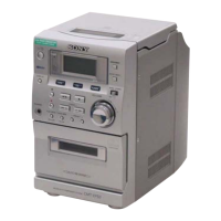
Covers component names and general product specs.

Model Variations

Lists supported regional models.

Document Revision History

Revision Log Details

Tracks changes made to the manual over time.

HCD-HP7 Service Manual Key Specifications

Main Unit Power Specifications

Details audio power output and distortion.

CD and Tape Player Specifications

Lists technical specs for CD and tape functions.

HCD-HP7 Tuner Specifications

FM and AM Tuner Details

Covers tuning ranges and intermediate frequencies.

General Power and Consumption Specs

Lists power requirements and consumption.

Service Manual Sections Overview

Disassembly Procedures

Details steps for taking the unit apart.

Assembly Procedures

Details steps for reassembling the unit.

Test Modes and Adjustments

Covers diagnostic modes and calibration procedures.

Servicing Notes and Safety Precautions

Component Repair and Handling Notes

Guidelines for repairing and handling sensitive parts.

Safety Checks and Leakage Tests

Procedures to ensure safe operation after service.

Unleaded Solder Usage

Recommendations for using lead-free solder.

General Information and Controls

Main Unit Button Locations

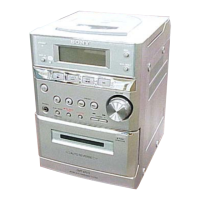
Identifies buttons on the main unit and their functions.

Remote Control Operations

Remote Control Button Functions

Lists buttons on the remote and their actions.

System Clock Setting

Instructions for setting the device's clock.

Disassembly Procedures Overview

Disassembly Flowchart

Visual guide to the disassembly sequence.

Disassembly - Outer Case and Front Panel

Case and Tape Mechanism Disassembly (3-1)

Steps to remove outer casing and tape deck.

Front Panel Section Disassembly (3-2)

Steps to remove the front panel.

Disassembly - Inner Panels

Panel Board Disassembly (3-3)

Steps to remove the panel board.

Back Panel Section Disassembly (3-4)

Steps to remove the back panel.

Disassembly - Main and Power Boards

Main Board Disassembly (3-5)

Steps to remove the main board.

Power AMP Board and Transformer Disassembly (3-6)

Steps to remove power amp and transformer.

Disassembly - CD Mechanism and Base Unit

CD Mechanism Deck Disassembly (3-7)

Steps to remove the CD mechanism.

Base Unit Section Disassembly (3-8)

Steps to remove the base unit section.

Disassembly - Base Unit and BD Board

Base Unit Disassembly (BU-K6BD71C) (3-9)

Steps to remove the base unit.

BD Board Disassembly (3-10)

Steps to remove the BD board.

Disassembly - Switch Boards

SW Board and Bracket Assembly Disassembly (3-12)

Steps to remove switch boards and bracket.

Disassembly - Connector and Stocker Motor

Connector Board Disassembly (3-13)

Steps to remove the connector board.

Stocker Motor Assembly Disassembly (3-14)

Steps to remove the stocker motor assembly.

Disassembly - Roller and Mode Motors

Roller Motor Assembly Disassembly (3-15)

Steps to remove the roller motor assembly.

Mode Motor Assembly Disassembly (3-16)

Steps to remove the mode motor assembly.

Disassembly - Rollers and Timing Belts

Rubber Roller Assembly Disassembly (3-17)

Steps to remove rubber roller assemblies.

Timing Belt Disassembly (3-18)

Steps to remove timing belts.

Disassembly - Cams and Sensors

Cam and Gear Disassembly (3-19)

Steps to remove cams and gears.

Sensor Board Disassembly (3-20)

Steps to remove the sensor board.

Assembly Procedures - Cam Installation

Installing Eject Lock Cam (4-1)

Steps to install the eject lock cam.

Installing Gear Cam (4-2)

Steps to install the gear cam.

Assembly Procedures - Gear Installation

Installing Mode C Gear (4-3)

Steps to install the mode C gear.

Installing Mode Cam Gear (4-4)

Steps to install the mode cam gear.

Assembly Procedures - Rotary Encoder and Stocker

Installing Rotary Encoder and Stocker Gear (4-5)

Steps for installing encoder and stocker gear.

Installing the Stocker Assembly (4-6)

Steps for installing the stocker assembly.

Test Modes

AM Channel, CD, and Tray Lock Modes

Covers AM step, CD ship, and disc tray lock modes.

Reset, Version, Panel, and MC Test Modes

Covers cold reset, version display, and panel/MC test modes.

Mechanical Adjustments

Tape Mechanism Deck Adjustments

Covers precautions and torque measurements for tape deck.

CD Service Mode Operations

Instructions for CD service mode.

Electrical Adjustments

Deck Section Azimuth Adjustment

Procedure for adjusting record/playback head azimuth.

CD Section Operations

Focus Bias Check Procedure

Steps for checking CD focus bias.

Diagrams and Schematics Overview

Circuit Board Locations

Identifies locations of various circuit boards.

Diagram and Schematic Conventions

Schematic Diagram Conventions

Explains symbols and notations used in schematics.

Printed Wiring Board Conventions

Explains symbols and notations for PWBs.

Waveform Examples

Shows typical oscilloscope waveforms.

BD Board Schematics

BD Board Schematic Diagram (8-3)

Detailed schematic for the BD board.

Printed Wiring Boards - Changer Section

Changer Section PWB Layout (8-4)

Layout of printed wiring board for the changer section.

Schematic Diagrams - Changer Section

Changer Section Schematic Diagram (8-5)

Detailed schematic for the changer section.

Printed Wiring Boards - Main Section

Main Section PWB Layout (8-6)

Layout of printed wiring board for the main section.

Schematic Diagrams - Main Section

Main Section Schematic Diagram (8-7)

Detailed schematic for the main section.

Printed Wiring Boards - Front Section

Front Section PWB Layout (8-8)

Layout of printed wiring board for the front section.

Schematic Diagrams - Front Section

Front Section Schematic Diagram (8-9)

Detailed schematic for the front section.

Printed Wiring Boards - PWR AMP/Power Section

PWR AMP/Power Section PWB Layout (8-10)

Layout of printed wiring board for PWR AMP/Power section.

Schematic Diagrams - PWR AMP/Power Section

PWR AMP/Power Section Schematic Diagram (8-11)

Detailed schematic for PWR AMP/Power section.

IC Block Diagrams

BD Board IC Block Diagrams (8-12)

Block diagrams for ICs on the BD board.

IC Block Diagrams - Panel Board

Panel Board IC Block Diagrams (IC602)

Block diagram for IC602 on the panel board.

IC Pin Functions and Diagrams

Main Board IC Pin Functions

Pin descriptions for main board ICs.

Power AMP Board IC Pin Functions

Pin descriptions for power AMP board ICs.

Connector Board IC Pin Functions

Pin descriptions for connector board ICs.

IC Pin Function Descriptions

IC601 Panel Board Pin Functions (8-13)

Pin details for IC601 on the panel board.

IC Pin Function Descriptions (Continued)

IC601 Panel Board Pin Functions (80-100)

Continues pin details for IC601 on the panel board.

Exploded Views and Parts Lists

Case, Top Panel, and Front Panel Exploded View (9-1)

Visual breakdown of outer casing parts.

Exploded Views and Parts Lists (Continued)

Front Panel Section Exploded View (9-2)

Visual breakdown of front panel components.

Exploded Views and Parts Lists (Continued)

Chassis Section-1 Exploded View (9-3)

Visual breakdown of chassis section parts.

Exploded Views and Parts Lists (Continued)

Chassis Section-2 Exploded View (9-4)

Visual breakdown of chassis section parts.

Exploded Views and Parts Lists (Continued)

CD Mechanism Section-1 Exploded View (9-5)

Visual breakdown of CD mechanism parts.

Exploded Views and Parts Lists (Continued)

CD Mechanism Section-2 Exploded View (9-6)

Visual breakdown of CD mechanism parts.

Exploded Views and Parts Lists (Continued)

CD Mechanism Section-3 Exploded View (9-7)

Visual breakdown of CD mechanism parts.

Exploded Views and Parts Lists (Continued)

CD Mechanism Section-4 Exploded View (9-8)

Visual breakdown of CD mechanism parts.

Exploded Views and Parts Lists (Continued)

CD Mechanism Section-5 Exploded View (9-9)

Visual breakdown of CD mechanism parts.

Exploded Views and Parts Lists (Continued)

CD Mechanism Section-6 Exploded View (9-10)

Visual breakdown of CD mechanism parts.

Exploded Views and Parts Lists (Continued)

Optical Pick-up Section Exploded View (9-11)

Visual breakdown of optical pick-up parts.

Electrical Parts List - BD Board

BD Board Components

List of capacitors, connectors, and ferrite beads for the BD board.

Electrical Parts List - Main Board Components

Main Board Capacitors, Connectors, Diodes

List of components for the main board.

Main Board ICs, Resistors, Transistors

List of components for the main board.

Electrical Parts List - Panel Board Components

Panel Board Capacitors, Connectors, Diodes

List of components for the panel board.

Panel Board ICs, Resistors, Transistors

List of components for the panel board.

Electrical Parts List - Various Board Components

Main Board Resistors and Transistors

List of components for the main board.

Panel Board Components

List of components for the panel board.

Electrical Parts List - Panel Board Components (Continued)

Panel Board Capacitors, Connectors, Diodes

List of components for the panel board.

Panel Board ICs, Resistors, Transistors

List of components for the panel board.

Electrical Parts List - Various Board Components (Continued)

Main Board Resistors and Transistors

List of components for the main board.

Panel Board Components

List of components for the panel board.

Electrical Parts List - Main Board Components (Continued)

Main Board Transistors and Resistors

List of components for the main board.

Main Board Diodes, ICs, and Connectors

List of components for the main board.

Electrical Parts List - Panel Board Components (Continued)

Panel Board Resistors and Switches

List of components for the panel board.

Panel Board Capacitors

List of components for the panel board.

Electrical Parts List - Panel Board Components (Continued)

Panel Board Capacitors, Connectors, Diodes

List of components for the panel board.

Panel Board ICs and Jacks

List of components for the panel board.

Electrical Parts List - Panel Board Components (Continued)

Panel Board Resistors and Vibrator

List of components for the panel board.

Panel Board ICs and Switches

List of components for the panel board.

Electrical Parts List - Panel Board Components (Continued)

Panel Board Capacitors, Connectors, Diodes

List of components for the panel board.

Panel Board Terminals, Fuses, ICs, Coils

List of components for the panel board.

Electrical Parts List - Power Amp and Sensor Board Components

Power Amp Board Transistors and Resistors

List of components for the power amp board.

Sensor Board Components

List of components for the sensor board.

Electrical Parts List - Miscellaneous and Switch Components

Stocker Motor, Sub Trans, and SW Board Parts

List of components for various boards.

Miscellaneous and Switch Components

List of miscellaneous parts and switches.

Revision History

Document Revision Log

Tracks changes made to the manual over time.

SS-CHP7 Speaker System Service Manual

Speaker System Specifications

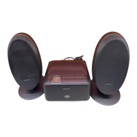
Lists technical specifications for the speaker system.

SS-CHP7 Exploded View and Parts List

L-CH Speaker Exploded View and Parts

Visual breakdown of L-CH speaker components.

SS-CHP7 Revision History

Document Revision Log

Tracks changes made to the manual over time.

Related product manuals