Do you have a question about the Sony SS-EC719iP and is the answer not in the manual?
Details power output and harmonic distortion metrics for various models.
Lists key parameters for inputs, outputs, CD player, tuner, dock, and USB interfaces.
Outlines essential safety checks, including AC leakage testing, before returning the unit.
Explains how to perform AC leakage tests using various measurement instruments.
Highlights critical components marked with ▲ that require exact replacement for safety.
Provides guidelines for handling optical pick-up blocks, laser diodes, and unleaded solder.
Details the necessary process for safely discharging capacitors to prevent electric shock.
Presents a clear flowchart detailing the sequential steps for disassembling the unit.
Provides instructions for the safe removal of the main board assembly.
Details the procedure for detaching the main board, including connectors and heatsinks.
Details the steps and components involved in safely removing the power board.
Outlines the method for checking the RF signal using an oscilloscope for diagnostics.
Details the power input section and various voltage control circuits on the main board.
Illustrates the MPEG decoder, USB, and tuner interface circuits.
Shows the microcontroller, mute circuit, and Apple authentication circuits.
Illustrates the audio amplifier driver stages and fan control circuits.
Illustrates the detailed circuitry of the power supply unit.
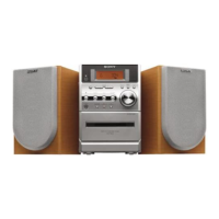
| Type | Stereo System |
|---|---|
| Brand | Sony |
| Model | SS-EC719iP |
| Speaker Configuration | 2-way |
| iPod Dock | Yes |
| Tuner | FM/AM |
| RMS Output Power | 100 Watts |
| Frequency Response | 40 Hz - 20 kHz |
| Connectivity | iPod Dock, USB |
| Playable Media | CD, USB |
| Playable File Formats | MP3, WMA |
| Frequency Response (Speaker) | 40 Hz - 20 kHz |