22
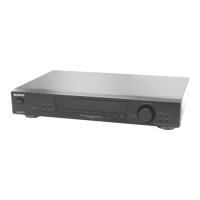
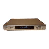
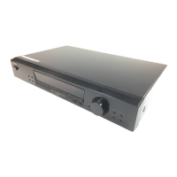
ST-S5
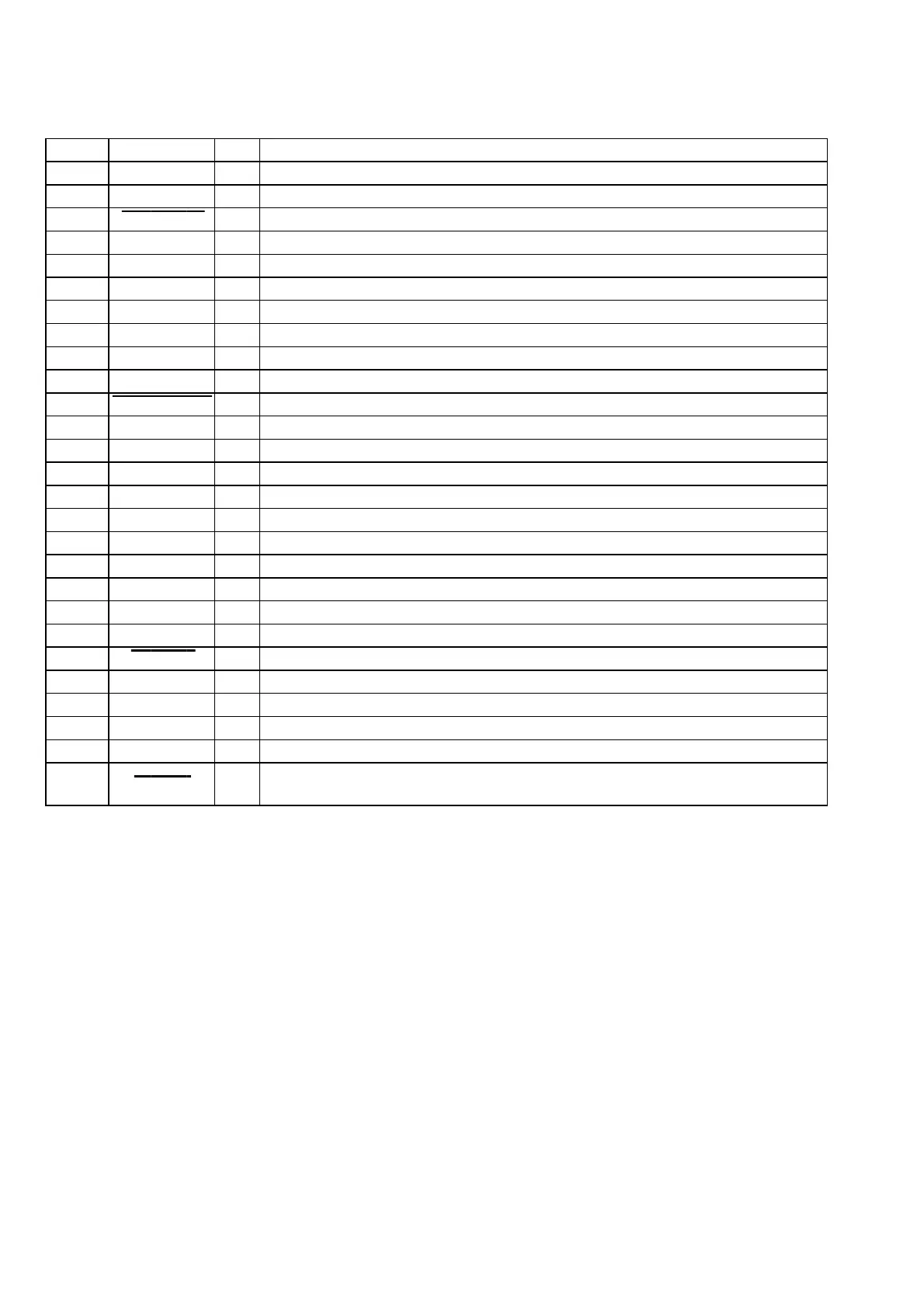
Pin No. Pin Name I/O Description
64
VSS — Ground terminal
65 to 70 ——
Not used (open)
71 LINE-MUTE
O Audio line muting on/off control signal output to the audio line circuit “L”: muting on
72 ——
Not used (open)
73 DISPLAY KEY I
DISPLAY switch (S601) input terminal
74 POWER KEY I
Power on/off switch in the TA-S7AV input terminal
75 DIR-UNLOCK
I PLL lock error and data error flag input from the digital audio interface receiver (IC604)
76 DIR-CS O
Chip enable signal output to the digital audio interface receiver (IC604)
77 DIR-XSTATE
I Source clock switching monitor input from the digital audio interface receiver (IC604)
78 DIR-RX
I Read data input from the digital audio interface receiver (IC604)
79 CODEC-SMUTE O
Soft muting on/off control signal output to the A/D, D/A converter (IC605) “L”: muting on
80 DSP-ACK
I Acknowledge signal input from the CXD9617R (IC601)
81 DSP-CS
O Chip select signal output to the CXD9617R (IC601)
82 DSP-DECODE
O Decode signal input from the CXD9617R (IC601)
83 to 86 ——
Not used (open)
87 STEREO I
FM stereo detection signal input from the FM/AM tuner unit “L”: stereo
88 TUNED I
Tuning detection signal input from the FM/AM tuner unit “L”: tuned
89 to 91 ——
Not used (open)
92 MODEL-IN
I Model setting terminal
93
SPEC-IN I Specification setting terminal
94 ——
Not used (open)
95 V-MUTE O
Video muting on/off control signal output terminal “L”: muting on Not used (open)
96
AVSS — Ground terminal
97 ——
Not used (open)
98
VREF
I
Reference voltage (+5V) input terminal
99 AVCC —
Power supply terminal (+5V)
100 AC-CUT I
AC cut on/off detection signal input from the reset signal generator (IC551)
“L”: AC cut on, “H”: AC cut off or checked


 To Next Page