23
ST-S5
• DSP BOARD IC601 CXD9617R (AUDIO DIGITAL SIGNAL PROCESSOR)
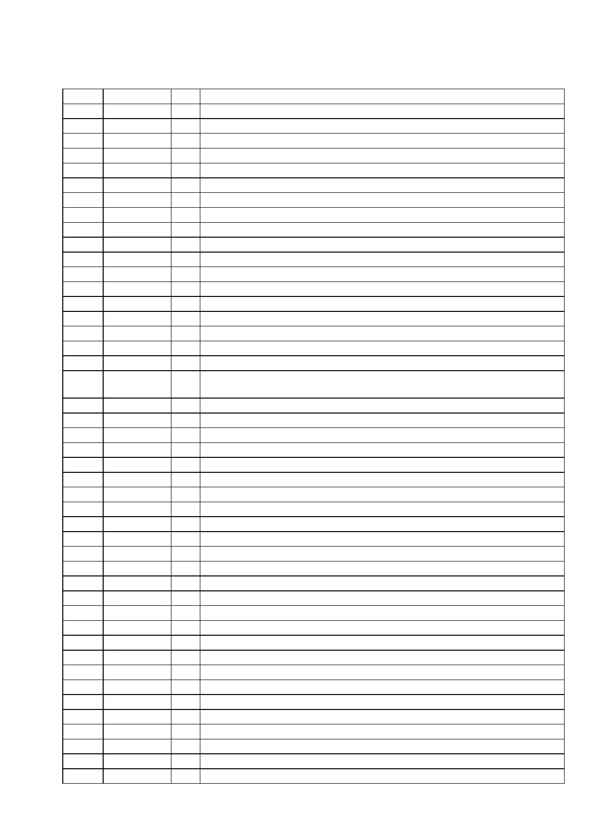
Pin No. Pin Name I/O Description
1
VSS —
Ground terminal
2
XRST I
Reset signal input from the M61512FP (IC607) “L”: reset
3
EXTIN I
Master clock signal input terminal Not used (fixed at “L”)
4
FS2 I
Sampling frequency selection signal input terminal Not used (fixed at “L”)
5 VDDI —
Power supply terminal (+2.6V)
6
FS1 I
Sampling frequency selection signal input terminal Not used (fixed at “L”)
7
PLOCK O
Internal PLL lock signal output terminal Not used (open)
8 VSS —
Ground terminal
9
MCLK1 I
Oscillation clock signal input from the digital audio interface receiver (IC604)
10
VDDI —
Power supply terminal (+2.6V)
11
VSS —
Ground terminal
12
MCLK2 O
Oscillation clock signal output terminal Not used (open)
13
MS I
Master/slave selection signal input terminal “L”: slave, “H”: master (fixed at “L” in this set)
14
SCKOUT O
Internal system clock signal output to the digital filter (IC606)
15
LRCKI1 I
L/R sampling clock signal (44.1 kHz) input terminal Not used (open)
16 VDDE —
Power supply terminal (+3.3V)
17
BCKI1 I
Bit clock signal (2.8224 MHz) input terminal Not used (open)
18
SDI1 I
Audio serial data input from the D/A, A/D converter (IC605)
19
LRCKO O
L/R sampling clock signal (44.1 kHz) output to the D/A, A/D converter (IC605) and digital filter
(IC606)
20
BCKO O
Bit clock signal (2.8224 MHz) output to the D/A, A/D converter (IC605) and digital filter (IC606)
21
VSS —
Ground terminal
22
KFSIO I
Audio clock signal input from the digital audio interface receiver (IC604)
23 to 25 SDO1 to SDO3 O
Audio serial data output to the A/D, D/A converter (IC604)
26
SDO4 O
Audio serial data output to the digital filter (IC606)
27
SPDIF O
S/PIDF signal output terminal Not used (open)
28
LRCKI2 I
L/R sampling clock signal (44.1 kHz) input from the digital audio interface receiver (IC604)
29
BCKI2 I
Bit clock signal (2.8224 MHz) input from the digital audio interface receiver (IC604)
30
SDI2 I
Audio serial data input from the digital audio interface receiver (IC604)
31
VSS —
Ground terminal
32
HACN O
Acknowledge signal output to the system controller (IC501)
33
HDIN I
Write data input from the system controller (IC501)
34
HCLK I
Clock signal input from the system controller (IC501)
35
HDOUT O
Read data output to the system controller (IC501)
36
HCS I
Chip select signal input from the system controller (IC501)
37
SDCLK O
Clock signal output terminal Not used (open)
38
CLKEN O
Clock enable signal output terminal Not used (open)
39
RAS O
Row address strobe signal input terminal Not used (open)
40
VDDI —
Power supply terminal (+2.6V)
41
VSS —
Ground terminal
42
CAS O
Column address strobe signal output terminal Not used (open)
43
DQM O
Output terminal of data input/output mask Not used (open)
44 CS0 O
Chip select signal output to the S-RAM (IC602)
45
WE0 O
Write enable signal output to the S-RAM (IC602)
46
VDDE —
Power supply terminal (+3.3V)
47
WMD1 I
S-RAM wait mode setting terminal Fixed at “H” in this set


 To Next Page