EasyManua.ls Logo

Sony ST-SP55 Service Manual

Sony ST-SP55
16 pages
To Next Page IconTo Next Page
Page #1 background imageLoading...
Page #1 background image
1
AEP Model
UK Model
E Model
SPECIFICATIONS
SERVICE MANUAL
MICRO Hi-Fi COMPONENT SYSTEM
ST-SP55
FM stereo, FM/AM superheterodyne tuner
Input
AUX IN (phono jacks): voltage 250 mV, impedance
47 kilohms
Output
AUX OUT (phono jacks): voltage 250 mV, impedance
1 kilohm
FM tuner section
Tuning range 87.5 – 108.0 MHz
(50 kHz step)
Aerial FM lead aerial
Aerial terminals 300 ohms unbalanced
Intermediate frequency 10.7 MHz
AM tuner section
Tuning range
European model: 531 – 1,602 kHz
(with the interval set at 9 kHz)
Other models: 531 – 1,602 kHz
(with the interval set at 9 kHz)
530 – 1,710 kHz
(with the interval set at 10 kHz)
Aerial AM loop aerial
External aerial terminals
Intermediate fre
q
uenc
y
450 kHz
General
Dimensions (w/h/d) incl. projecting parts and controls
Approx. 202 × 75 × 291 mm
Mass
Approx. 1.3 kg
Design and specifications are subject to change
without notice.
ST-SP55 is the tuner section
in CMT-SP55MD or CMT-SP55TC.
www.freeservicemanuals.info
05/28/2012
World of Free Manuals
Question and Answer IconNeed help?

Do you have a question about the Sony ST-SP55 and is the answer not in the manual?

Sony ST-SP55 Specifications

General IconGeneral
BrandSony
ModelST-SP55
Tuning Range FM87.5 - 108 MHz
Tuning Range AM530 - 1710 kHz
Distortion0.3%
Preset Stations30

Summary

Specifications

General Specifications

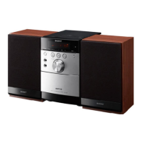
Physical dimensions and weight of the unit.

FM Tuner Section Specifications

Technical specifications for FM reception tuning range and frequency.

AM Tuner Section Specifications

Technical specifications for AM reception tuning range and frequency.

Section 3 Diagrams

Waveforms

Visual representations of electrical signals at specific test points.

Circuit Boards Location

Identification of main circuit boards within the unit.

Block Diagram

Overall functional block representation of the tuner section.

Schematic Diagram - Main Section

Detailed electrical schematic for the main component board.

Printed Wiring Board - Main Section

Layout of components and traces on the main circuit board.

Schematic Diagram - Panel Section

Electrical schematic for the panel interface components.

Printed Wiring Board - Panel Section

Component layout for the panel interface circuit board.

IC Pin Functions

Detailed pin assignments and functions for integrated circuits.

IC Block Diagram

Functional block representation of specific integrated circuits.

Section 1 Service Note

CD Text Display Information

Information regarding CD text display limitations and behavior.

Cold Reset Procedure

Steps to reset the unit to factory default settings.

Hot Reset Procedure

Steps to reset stored preset data without a full cold reset.

GC Test Mode

Instructions for entering and operating the general control test mode.

Section 2 General

Button and Display Overview

Identification and function of front panel buttons and display elements.

Section 4 Exploded View

Case and Front Panel Assembly

Exploded diagram showing the case and front panel components.

Section 5 Electrical Parts List

Related product manuals