EasyManua.ls Logo

Sony TA-F870ES Service Manual

Sony TA-F870ES
28 pages
To Next Page IconTo Next Page
Page #1 background imageLoading...
Page #1 background image
TA-FSSSESL/FTTDES/FTOES
SERVICE
MANUAL
AEP
Model
UK
Model
TA-F770ES
E
Model
TA-F333ESL
Germany
Model
TA-F770ES/F870ES
Photo:
TA-F333ESL
SPECIFICATIONS
Amplifier
Section
TA-F870ES
TA-F333ESL/TA-F770ES
Continuous
RMS
power
4
ohms,
Countries
other
|
170W
+170
W
140W+140W
output
(both
channels
driven
|
20
Hz
20
kHz
|
than
North
(THD
0.02%)
(THD
0.02%)
simulataneously)
European
(DIN:
200
W
+
200
W)
(DIN:
180
W
+
180
W)
Countries
North
European
countries
110W+110
W
(THD
0.018%)
(DIN:
130
W
+
130
W)
120W
+120
W
100
W
+100
W
(THD
0.004%)
(THD
0.015%)
(DIN:
135
W
+
135
W)
(DIN:
120
W
+
120
W)
6
ohms,
20
Hz
20
kHz
Countries
other
than
North
European
countries
North
90
W:+
90
W
European
(THD
0.015%)
countries
(DIN:
105
W
+
105
W)
Power
band
width
(IHF)
8
ohms,
THD
0.02%
10
Hz
100
kHz
at
45
W.
10
Hz
100
kHz
at
45
W
(78
IHF)
Total
harmonic
distortion
8
ohms,
at
10
watt
output
0.003% 0.003%
intermodulation
(IM)
4
ohms,
at
rated
output
0.008% 0.008%
distortion
60
Hz:
7
kHz
=4:1
6
ohms,
at
rated
output
0.006%
8
ohms,
at
rated
output
0.004%
Damping
factor
8
ohms,
at
1
kHz
swoo0—“—~—s~dO
~
Continued
on
next
page
INTEGRATED
STEREO
AMPLIFIER
ONY.
8
ohms,
20
Hz
20
kHz
Question and Answer IconNeed help?

Do you have a question about the Sony TA-F870ES and is the answer not in the manual?

Sony TA-F870ES Specifications

General IconGeneral
BrandSony
ModelTA-F870ES
CategoryAmplifier
LanguageEnglish

Summary

GENERAL

Front Panel Controls

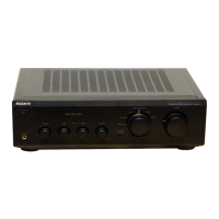
Explanation of the front panel controls and their specific functions.

Operating Voltage and AC Outlet

Information on voltage requirements and AC outlet specifications for operation.

DISASSEMBLY

SWITCH DISASSEMBLY AND ASSEMBLY

ELECTRICAL ADJUSTMENTS

Offset Adjustment

Procedure for performing the offset voltage adjustment on the amplifier.

Bias Current Adjustment

Procedure for performing the bias current adjustment on the amplifier.

DIAGRAMS

Block Diagram

Overall system block diagram illustrating signal flow and component interaction.

Circuit Boards Location

Identification of physical locations for the amplifier's various circuit boards.

Schematic Diagram

Detailed circuit schematic diagrams for troubleshooting and repair.

EXPLODED VIEWS

ELECTRICAL PARTS LIST

Main Board Components

Lists of components for Main (A) and Main (B) circuit boards.

Related product manuals