EasyManua.ls Logo

Sony TA-F830ES Service Manual

Sony TA-F830ES
17 pages
To Next Page IconTo Next Page
Page #1 background imageLoading...
Page #1 background image
Suso
%
Posen
"
INTEGRATED
STERIO
AMPRPER
SONNE
108
Bae
830ES
A
seutcton
nz
Germany
Model
SPECIFICATIONS
|
Daten
MeBbedingungen
Sinus-
4
Ohm,
20
Hz
-
20
kHz
180
W
+
180
W
Dauerleistung
Klirrgrad
0,008%
(DIN:
210
W
+
210
W)
(beide
Kanale
=f
Ohm,
20
Hz
-
20
kHz
|
150
W
+
150
W
gleichzeitig
Klirrgrad
0,006%
(DIN:
170
W
+
170
W)
angesteuert)
120
W
+120
W
(DIN:
145
W
+
145
W)
10
Hz
-
100
kHz
bei
90
W
10
Hz
-
100
kHz
bei
60
W
8
Ohm,
bei
10
W
0,002%
Ausgangsleistung
0,008%
8
Ohm,
20
Hz
-
20
kHz
Klirrgrad
0,004%
4
Ohm,
THD
0,04%
Leistungsband-
breite
(IHF)
8
Ohm,
THD
0,04%
Dynamik-
Kopfraum
(78
IHF)
Gesamtklirrgrad
Intermodulations-
verzerrung
(1M)
60
Hz:
7
kHz
=
4:4
4
Ohm,
bei
Nennausgangsieistung
6
Ohm,
bei
0,006%
Nennausgangsleistung
8
Ohm,
bei
10,0D4%
Nennausgangsleistung
;
Dampfungstaktor
|8
Ohm,
1
kHz
Eigenrauschen
Netzwerk
A
Frequenzgang
PHONO
MM
RIAA-
Entzerrungskurve
+0,2
dB
TUNER,
CD,
TAPE
1,
2,
|
2
Hz
-
200
kHz
3,
DIRECT
IN
+8
dB
PHONO
|
MC
0,17
mV,
33
Ohm
0,17
mV,
100
Ohm
2,5
mV,.50
kKOhm
150
mV,
50
kOhm
Eingangsemp-
findlichkeit
TUNER,
CD,
DIRECT
IN,
TAPE
1,
2, 3,
ADAPTOR
IN
PHONO
|
MC
78
dB*,
70
dB
(A)
MM.
[80
dB*,
87
48
(A)
TUNER,
CD,
DIRECT
|
84
dB*,
105
dB
(A)
IN,
TAPE
1,
2,
3,
ADAPTOR
IN
S/R
(Netzwerk
*
78
(IHF)
continued
on
next
page
INTEGRATED
STEREO
AMPLIFIER
SON
Y.
Question and Answer IconNeed help?

Do you have a question about the Sony TA-F830ES and is the answer not in the manual?

Sony TA-F830ES Specifications

General IconGeneral
BrandSony
ModelTA-F830ES
CategoryAmplifier
LanguageEnglish

Summary

Specifications

Safety-Related Component Warning!!

Block Diagram

Section 1 General

Front Panel Controls and Connectors

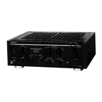
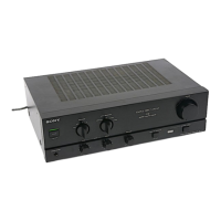
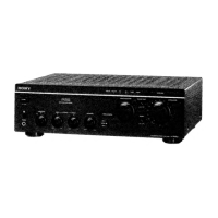
Details controls, switches, and connectors located on the front panel (items 1-20).

Rear Panel Connectors

Details input and output connectors found on the rear panel (items 21-29).

Section 2 Disassembly

Main Board Inspection Procedures

Procedures for inspecting main and EQ MA boards during disassembly.

Case and Panel Disassembly

Outlines steps for disassembling the amplifier's case, front, and back panels.

Section 3 Removal Switch Block

Switch Block Removal and Attachment

Procedures for removing and attaching switch blocks, including diagrams.

Section 4 Electrical Adjustments

Offset and Bias Adjustment Procedures

Details offset and bias adjustment steps for optimal performance.

Section 5 Diagrams

Semiconductor Lead Layouts

Shows lead configurations for various semiconductor components used in the unit.

Schematic Diagrams

Detailed circuit schematics illustrating the amplifier's internal electronic design.

Circuit Diagrams Location

Index to locate specific circuit diagrams within the manual for reference.

Section 6 Exploded Views

Case Assembly Exploded View

Detailed exploded view of the amplifier's case and its constituent parts.

Front and Back Panel Assemblies

Exploded view illustrating the construction of the front chassis and back panel assemblies.

Main Chassis Assembly Exploded View

Exploded view detailing the assembly of the main chassis and its connected components.

Section 7 Electrical Parts List

Accessory & Packing Material

Related product manuals