Do you have a question about the Sony TA-FE230 and is the answer not in the manual?
| Speaker load impedance | 4 - 16 ohms |
|---|---|
| Total Harmonic Distortion (THD) | 0.03% |
| Signal-to-Noise Ratio | 100 dB |
| Inputs | 4 x Line In, 1 x Phono |
| Outputs | Tape1, Tape2 |
| Dimensions | 430 x 135 x 320 mm |
| Input sensitivity | 150mV (line) |
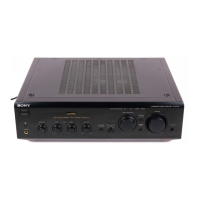
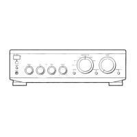
Details the front and rear panel controls and their functions for easy identification.
Procedure for removing the outer case of the amplifier unit for servicing.
Steps to detach the front panel assembly from the main chassis.
Explains notation and conventions used in wiring boards and schematic diagrams.
Layout of components and traces on the MAIN printed wiring board.
Electrical schematic for the MAIN board, detailing circuit connections and components.
Component and trace layout for the PANEL sections of the unit.
Schematic diagram illustrating the circuitry of the panel sections.
Printed wiring board layouts for the power supply and related sections.
Schematic diagram for the power supply and related circuit boards.
Detailed pinout and function descriptions for integrated circuits used in the unit.
Exploded diagram showing parts and assembly for the main case section.
Exploded diagram detailing parts and assembly for the front panel section.
Exploded diagram illustrating the components and assembly of the chassis section.
Lists electrical components for the Control board and related AC boards.
Lists electrical components for the Main board of the amplifier.
Lists components for Power Supply, H.P. Board, and other ancillary boards.