EasyManua.ls Logo

Sony TA-SP55 Service Manual

Sony TA-SP55
20 pages
To Next Page IconTo Next Page
Page #1 background imageLoading...
Page #1 background image
1
AEP Model
UK Model
E Model
SPECIFICATIONS
SERVICE MANUAL
MICRO Hi-Fi COMPONENT SYSTEM
TA-SP55
TA-SP55 is the amplifier section
in CMT-SP55MD or CMT-SP55TC.
European model:
DIN power output (Rated): 25 + 25 watts (8 ohms at 1 kHz,
DIN, 230 V)
Continuous RMS power output (Reference):
30 + 30 watts (8 ohms at 1 kHz,
10% THD, 230 V)
Music power output (Reference):
75 + 75 watts
General
Power requirements
European model: 230 V AC, 50/60 Hz
Other models: 110 – 120 V or 220 – 240 V
AC, 50/60 Hz
Power consumption 70 watts
Dimensions (w/h/d)
Mass Approx.
Approx. 202 x 101 x 306 mm
3.9 kg
Design and specifications are subject to change
without notice.
Other models:
DIN power output (Rated): 25 + 25 watts (8 ohms at 1 kHz,
DIN, 240 V)
22 + 22 watts (8 ohms at 1 kHz,
DIN, 220 V)
Continuous RMS power output (Reference):
30 + 30 watts (8 ohms at 1 kHz,
10% THD, 240 V)
28 + 28 watts (8 ohms at 1 kHz,
10% THD, 220 V)
Output
PHONES (stereo phono jack):
accepts headphones of 8 ohms or
more.
w
w
w
.
x
i
a
o
y
u
1
6
3
.
c
o
m
Q
Q
3
7
6
3
1
5
1
5
0
9
9
2
8
9
4
2
9
8
T
E
L
1
3
9
4
2
2
9
6
5
1
3
9
9
2
8
9
4
2
9
8
0
5
1
5
1
3
6
7
3
Q
Q
TEL 13942296513 QQ 376315150 892498299
http://www.xiaoyu163.com
Question and Answer IconNeed help?

Do you have a question about the Sony TA-SP55 and is the answer not in the manual?

Sony TA-SP55 Specifications

General IconGeneral
BrandSony
ModelTA-SP55
CategoryStereo System
LanguageEnglish

Summary

Specifications

Safety Related Component Warning

Section 1 Servicing Note

Cold Reset Procedure

Procedure to reset all data to initial conditions.

GC Test Mode Operation

Procedure for entering and using the GC Test Mode.

MC Test Mode Operation

Procedure for entering and using the MC Test Mode.

Section 2 General

Setting the System Time

Steps to set the internal clock for timer functions.

Section 3 Disassembly

3-1. Case Disassembly

Instructions for disassembling the main case.

3-2. Front Panel Assembly Disassembly

Instructions for disassembling the front panel assembly.

Section 4 Diagrams

Section 6 Electrical Parts List

Semiconductor Components

List of semiconductor components with part numbers and locations.

Capacitor Components

List of capacitor components with part numbers and specifications.
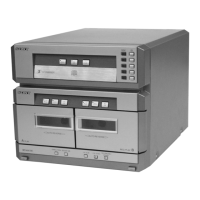
Related product manuals