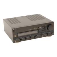
The Sony TA-V50 is an integrated stereo amplifier, serving as the amplifier unit for the LBT-V50W system. It is available in AEP, UK, and E models, each with specific power requirements and output configurations.
Function Description:
The TA-V50 is designed to amplify audio signals from various sources and output them to speakers or headphones. It features a comprehensive set of controls for input selection, volume adjustment, and sound equalization, allowing users to customize their listening experience.
Important Technical Specifications:
- Power Output:
- Continuous RMS Power Output (AEP, G-AEP, UK model):
- 50 + 50 watts (6 ohms, at 1 kHz, 0.5% THD)
- 40 + 40 watts (6 ohms, 40 Hz - 20 kHz, 0.5% THD)
- Music Power Output (E model): 160 W (6 ohms, 5% THD)
- Peak Music Power Output (E model): 320 W (6 ohms)
- Power Requirements:
- AEP model: 220V AC, 50/60Hz
- UK model: 240V AC, 50/60Hz
- E model: 120, 220, or 240V AC adjustable, 50/60Hz
- Power Consumption:
- AEP model: 110 watts
- UK model: 230 watts
- E model: 110 watts
- AC Outlets:
- AEP model: 2 unswitched, 100 watts max.
- UK model: 2 switched, 100 watts max.
- E model: 2 unswitched, 100 watts max.
- Inputs:
- PHONO (phono jacks): Sensitivity 2mV, Impedance 50 kilohms
- CD, VIDEO (AUDIO IN) (phono jacks): Sensitivity 150mV, Impedance 50 kilohms
- MIC (phone jack): Sensitivity 2mV, Impedance 20 kilohms
- Outputs:
- HEADPHONES (stereo phone jack): Accepts headphones of 8 ohms or more
- SPEAKER: Accepts speakers of 6 to 16 ohms
- Frequency Response:
- PHONO: RIAA curve ± 0.5 dB
- CD, VIDEO (AUDIO IN): 15 Hz - 50 kHz ± 3 dB
- MIC: 100 Hz - 10 kHz ± 3 dB
- Dimensions (w/h/d): Approx. 355 x 98 x 290 mm (14 x 4-1/8 x 9-7/8 inches), including projecting parts and controls.
- Weight: Approx. 5.8 kg (11 lb 15 oz) net.
Usage Features:
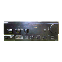
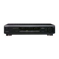
The TA-V50 offers a user-friendly interface with clearly labeled controls for various functions:
- POWER switch: Toggles the stereo system on and off.
- FUNCTION indicators: LEDs illuminate to show the currently selected input source (PHONO, TUNER, CD, TAPE, VIDEO/AUX).
- GRAPHIC EQUALIZER controls: Seven sliders allow for precise adjustment of frequency bands (100 Hz, 250 Hz, 500 Hz, 1 kHz, 3 kHz, 6 kHz, 14 kHz). These controls can boost or cut bass, adjust middle and low frequencies, enhance vocal presence, brighten sound, and reduce high-frequency noise like tape hiss. A central position on each slider ensures original tone quality.
- HEADPHONES jack: For connecting stereo headphones.
- MIC (microphone) jack: For connecting a microphone, enabling microphone mixing with the program source.
- MIXING control: Adjusts the balance between microphone volume and program source volume. Sliding towards "MIC" increases microphone volume, while sliding towards "SOURCE" increases source volume. When not in use, it should be set fully to "SOURCE."
- BALANCE control: Adjusts the left and right channel output levels.
- GRAPHIC EQUALIZER switch: Activates or deactivates the graphic equalizer controls. When off, the original tone quality is restored.
- FUNCTION select buttons: Dedicated buttons for selecting the desired program source:
- VIDEO/AUX: For video programs or other sources connected to VIDEO inputs.
- TAPE: For tape programs.
- CD: For programs connected to CD inputs.
- TUNER: For radio programs.
- PHONO: For disc programs connected to PHONO inputs.
- VOLUME control: Adjusts the overall output volume.
- System Control Terminals: Two 13-pin terminals for system integration.
Maintenance Features:
The manual highlights important safety and maintenance considerations:
- Safety-Related Components: Components identified by shading and a "A" mark on schematic diagrams and parts lists are critical for safe operation. These components must be replaced only with genuine Sony parts whose part numbers appear in the manual or supplements.
- Nonflammable Resistors: Indicated in the schematic diagrams.
- Capacitor and Resistor Specifications: All capacitors are in µF unless otherwise noted (PF: µµF; 50 WV or less are not indicated except for electrolytics and tantalums). All resistors are in Ω and 1/4W or less unless otherwise specified.
- Voltage Readings: Voltages are DC with respect to ground unless otherwise noted, and readings are taken with a VOM (50 kΩ/V).
- Mounting Diagram Notes: Includes information on the color code of sleeving over the end of the jacket and parts extracted from the component side.
- Semiconductor Lead Layouts: Refer to page 5 for details on semiconductor lead layouts.
- Parts Availability: Items marked with an asterisk (*) are not typically stocked for routine service and may require longer delivery times.
- Assembled Parts: Construction parts of an assembled unit are indicated with a collation number in the remark column.