EasyManua.ls Logo

Sony TC-C5 - Adjustments

Sony TC-C5
41 pages
Print Icon
To Next Page IconTo Next Page
To Previous Page IconTo Previous Page
Loading...
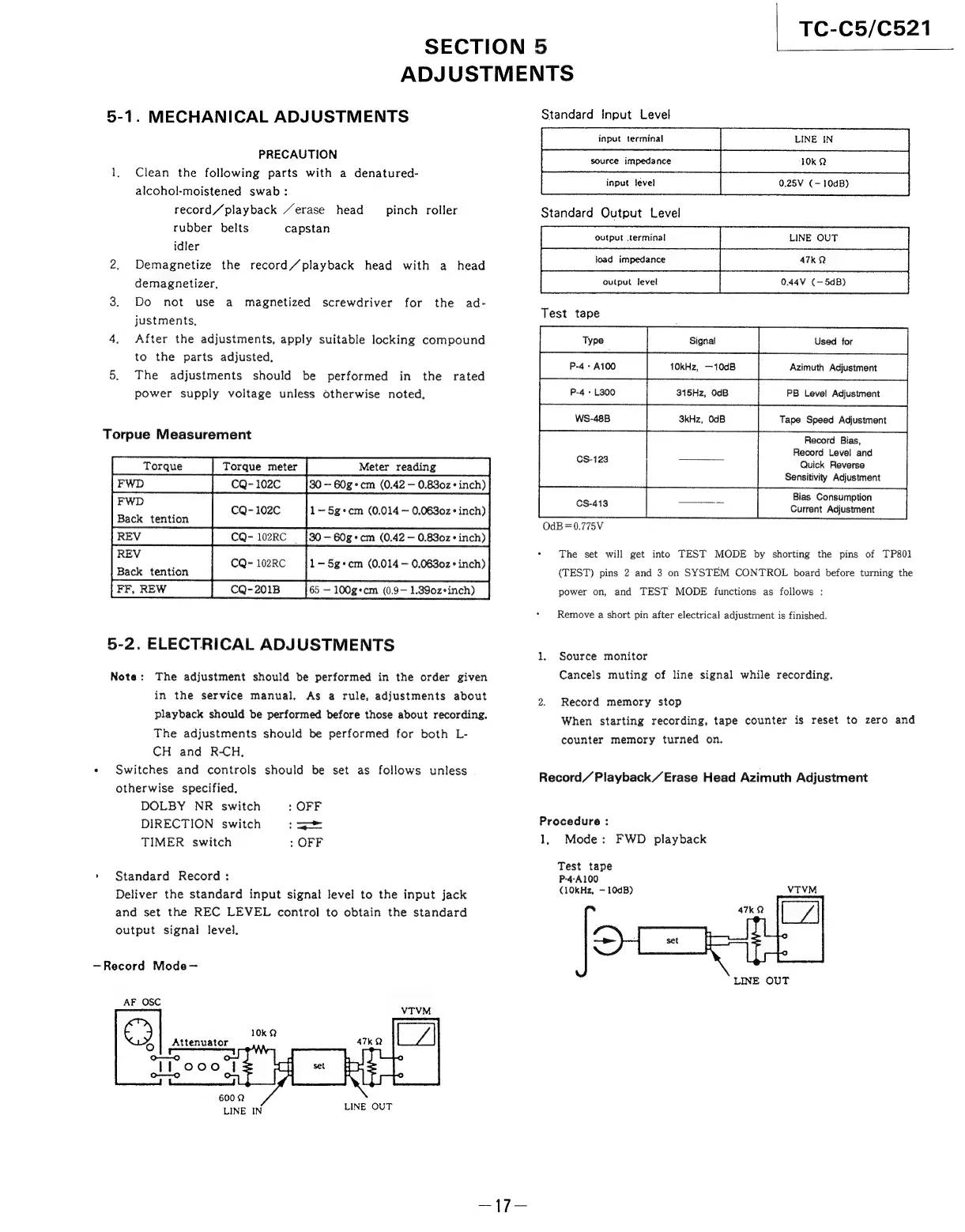
SECTION
5
TC-C5/C521
ADJUSTMENTS
5-1.
MECHANICAL
ADJUSTMENTS
PRECAUTION
1,
Clean
the
following
parts
with
a
denatured-
alcohol-moistened
swab:
record/playback
“erase
head
rubber
belts
capstan
idler
2.
Demagnetize
the
record/playback
head
with
a
head
demagnetizer,
pinch
roller
3.
Do
not
use
a
magnetized
screwdriver
for
the
ad-
justments,
4.
After
the
adjustments,
apply
suitable
locking
compound
to
the
parts
adjusted,
5.
The
adjustments
should
be
performed
in
the
rated
power
supply
voltage
unless
otherwise
noted.
Torpue
Measurement
CQ-102C
_
{30-60g+cm
(0.42
—
0.8302
inch)
FWD
.
CQ-102C
1~5g+cm
(0.014
~
0.0630z+
inch)
Back
tention
RE
30
—
60g+cm
(0.42
—
0.830z°
inch)
REV
:
CQ-
102RC
1—5g°cm
(0.014
—
0.0630z°
inch)
Back
tention
FF,
REW
CQ-201B
65
—
100g*°cm
(0.9—
1.390z*inch)
5-2.
ELECTRICAL
ADJUSTMENTS
Note:
The
adjustment
should
be
performed
in
the
order
given
in
the
service
manual.
As
a
rule,
adjustments
about
playback
should
be
performed
before
those
about
recording.
The
adjustments
should
be
performed
for
both
L-
CH
and
RCH.
«
Switches
and
controls
should
be
set
as
follows
unless
otherwise
specified,
DOLBY
NR
switch
:
OFF
DIRECTION
switch
—-
TIMER
switch
:
OFF
»
Standard
Record:
Deliver
the
standard
input
signal
level
to
the
input
jack
and
set
the
REC
LEVEL
control
to
obtain
the
standard
output
signal
level.
—Record
Mode—
AF
OSC
He,
Attenuator
oD
VTVM
LINE
IN
LINE
OUT
Standard
Input
Level
Standard
Output
Level
Test
tape
[se
fe
Record
Bias,
Record
Level
and
CS-123
a
Quick
Reverse
Sensitivity
Adjustment
Bias
Consumption
Current
Adjustment
The
set
will
get
into
TEST
MODE
by
shorting
the
pins
of
TP801
(TEST)
pins
2
and
3
on
SYSTEM
CONTROL
board
before
turning
the
power
on,
and
TEST
MODE
functions
as
follows
:
OdB
=0.775V
Remove
a
short
pin
after
electrical
adjustment
is
finished.
1.
Source
monitor
Cancels
muting
of
line
signal
while
recording.
2.
Record
memory
stop
When
starting
recording,
tape
counter
is
reset
to
zero
and
counter
memory
turned
on.
Record
Playback
Erase
Head
Azimuth
Adjustment
Procedure
:
1,
Mode:
FWD
playback
Test
tape
P-4-A100
(10kHz,
—
10dB)
VTVM
LINE
OUT