EasyManua.ls Logo

Sony TC-C5 - Page 17

Sony TC-C5
41 pages
Print Icon
To Next Page IconTo Next Page
To Previous Page IconTo Previous Page
Loading...
TC-C5/C521
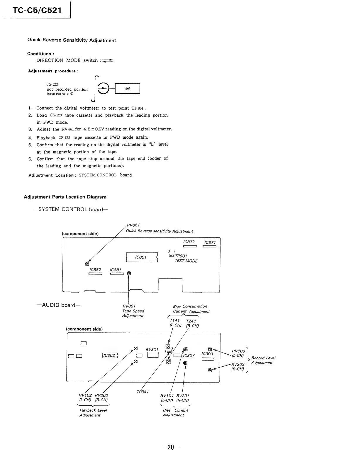
Quick
Reverse
Sensitivity
Adjustment
Conditions
:
DIRECTION
MODE
switch
:3==
Adjustment
procedure:
CS-123
not
recorded
portion
>
set
(tape
top
or
end)
Connect
the
digital
voltmeter
to
test
point
TP
861.
2.
Load
CS-123
tape
cassette
and
playback
the
leading
portion
in
FWD
mode.
3.
Adjust
the
RV861
for
4.5
+0.5V
reading
on
the
digital
voltmeter.
Playback
CS-123
tape
cassette
in
FWD
mode
again.
Confirm
that
the
reading
on
the
digital
voltmeter
is
“L”
level
at
the
magnetic
portion
of
the
tape.
6.
Confirm
that
the
tape
stop
around
the
tape
end
(boder
of
the
leading
and
the
magnetic
portions).
Adjustment
Location
:
SYSTEM
CONTROL
board
Adjustment
Parts
Location
Diagrsm
—SYSTEM
CONTROL
board—
RV861
3
Quick
Reverse
sensitivit
I
icompotierit-side)
itivity
Adjustment
1C872
/C871
—
co
3
7
TP801
TEST
MODE
—AUDIO
board—
RV881
Bias
Consumption
Tape
Speed
Current
Adjustment
Adjustment
7141
7241
:
(L-CH)
(R-
CH)
(component
side)
RV103
(L-CH)
Record
Level
RV203
Adjustment
TP341
RV102
RV202
RV101
RV201
(L-CH)
(R-CH)
{L-CH}
(R-CH)
So
Soa
Playback
Level
Bias
Current
Adjustment
Adjustment