EasyManua.ls Logo

Sony TC-FX205 - Leakage Test

Sony TC-FX205
18 pages
Print Icon
To Next Page IconTo Next Page
To Previous Page IconTo Previous Page
Loading...
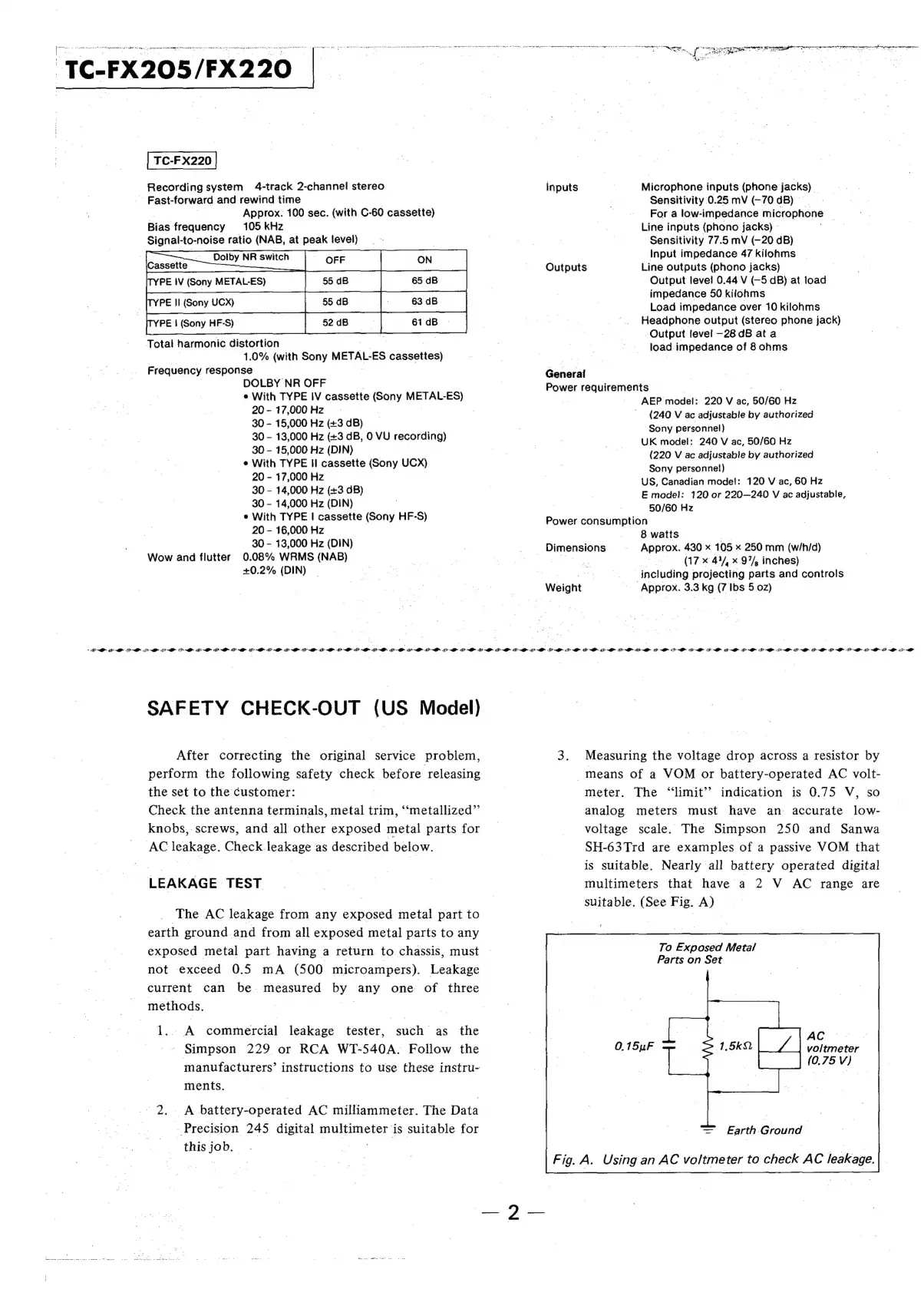
Recording
system
4-track
2-channel
stereo
-
Fast-forward
and
rewind
time
|
. |
Approx.
100
sec.
(with
C-60
cassette)
Bias
frequency
105
kHz
Signal-to-noise
ratio
(NAB,
at
peak
level)
PE
|
(Sony
HF-S)
Total
harmonic
distortion
a:
_
-
1.0%
(with
Sony
METAL-ES
cassettes)
Frequency
response
|
.
DOLBY
NR
OFF
.
¢
With
TYPE
IV
cassette
(Sony
METAL-ES)
20-17,000HZ
|
: ; ;
30
-
15,000
Hz
(+3
dB)
30
-
13,000
Hz
(+3
dB,
0
VU
recording)
30
-
15,000
Hz
(DIN)
|
e
With
TYPE
Il
cassette
(Sony
UCX)
20
-
17,000
Hz
30
-
14,000
Hz
(+3
dB)
30
-
14,000
Hz
(DIN)
e
With
TYPE
|
cassette
(Sony
HF-S)
20
-
16,000
Hz
|
30
-
13,000
Hz
(DIN)
Wow
and
flutter
0.08%
WRMS
(NAB)
+0.2%
(DIN)
So
seer
nee
care
are
ements
coat
gar
ee
TTT
TT
aN
AM
TE
poor
a
pty
Soegag
rts
ere
tet
oe
re
oe
rn
er
ne
nmr
ort
ei
a
Bae
Seger
Oy
:
5
Pe
ce
Ae
Inputs
Microphone
inputs
(phone
jacks)
©
Sensitivity
0.25
mV
(-70
dB)
For
a
low-impedance
microphone
©
Line
inputs
(phono
jacks)
»
Sensitivity
77.5
mV
(-20
dB)
Input
impedance
47
kilohms
Outputs
Line
outputs
(phono
jacks)
Output
jeve!l
0.44
V
(-5
dB)
at
load
impedance
50
kifohms
Load
impedance
over
10
kilohms
Headphone
output
(stereo
phone
jack)
Output
fevel
—28
dB
at
a
load
impedance
of
8
ohms
Generai
Power
requirements
.
7
AEP
model:
220
V
ac,
50/60
Hz
(240
V
ac
adjustable
by
authorized
Sony
personnel)
UK
model:
240
V
ac,
50/60
Hz
(220
V
ac
adjustable
by
authorized
Sony
personne!)
US,
Canadian
model:
120
V
ac,
60
Hz
E
model:
120
or
220—240
V
ac
adjustable,
50/60
Hz
Power
consumption
8
watts
-
_
Dimensions
Approx.
430
x
105
x
250
mm
(w/h/d)
a
(17
*
44/,
x
97%,
inches)
i
ni
og
te
including
projecting
parts
and
controls
Weight
Approx.
3.3
kg
(7
Ibs
5
02)
TAN
LT
RN
RS
RL
Te
QD
RL
RTL
RE
A
DR
lt
1D
tlt
ald
st
a
PAN
=
a
AL
RB
ND
RI
RR
RL
RU
LL
ND
gl
RL
RN
RD
8
RD
A
A
RT
A
RE
RT
DE
ET
dT
RT
lO
a
pl
all
I
SAFETY
CHECK-OUT
(US
Model)
After
correcting
the
original
service
problem,
perform
the
following
safety
check
before
releasing
the
set
to
the
customer:
|
Check
the
antenna
terminals,
metal
trim,
‘‘metallized”’
knobs,.
screws,
and
all
other
exposed
metal
parts
for
AC
leakage.
Check
leakage
as
described
below.
LEAKAGE
TEST
The
AC
leakage
from
any
exposed
metal
part
to
earth
ground
and
from
all
exposed
metal
parts
to
any
exposed
metal
part
having
a
return
to
chassis,
must
not
exceed
0.5
mA
(500
microampers).
Leakage
current
can
be
measured
by
any
one
of
three
methods.
|
1.
A
commercial
leakage
tester,
such
as
the
'
Simpson
229
or
RCA
WT-540A.
Follow
the
manufacturers’
instructions
to
use
these
instru-
ments.
2.
°
A
battery-operated
AC
milliammeter.
The
Data
-
Precision
245
digital
multimeter
is
suitable
for
thisjob.
.
-
3.
Measuring
the
voltage
drop
across
a
resistor
by
means
of
a
VOM
or
battery-operated
AC
volt-
meter.
The
“limit”
indication
is
0.75
V,
so
analog
meters
must
have
an
accurate
low-
voltage
scale.
The
Simpson
250
and
Sanwa
SH-63Trd
are
examples
of
a
passive
VOM
that
is
suitable.
Nearly
all
battery
operated
digital
multimeters
that
have
a
2
V
AC
range
are
suitable.
(See
Fig.
A)
To
Exposed
Metal
Parts
on
Set
AC
voltmeter
(0.75
V)
=
Earth.Ground
Using
an
AC
voltmeter
to
check
AC
leakage.