EasyManua.ls Logo

Sony TC-FX205 - Electrical Adjustments

Sony TC-FX205
18 pages
Print Icon
To Next Page IconTo Next Page
To Previous Page IconTo Previous Page
Loading...
‘TC-FX205/FX220
|
SECTION
3
ADJUSTMENTS
|
3-1..
MECHANICAL
ADJUSTMENTS
No
mechanical
adjustments
applied
to
this
unit.
-_@
Torque
Measurement
[___Mede
|
TorqueMeter
|
Torque
|
|
40
—70g-cm
CQ-102C
(0.55
—
0.97
oz+inch)
|
70
—150g*cm
.
|
70
—
150
g*cm
ee
ia
(0.97
—
2.07
oz+inch)
|
Fworack
|
co
igac
eee
cn
_
|
tension
:
(
0.028
—
0.083
ozeinch)
»
3-2,
ELECTRICAL
ADJUSTMENTS
Note:
The
adjustment
should
be
performed
in
the
order
given
in
this
service
manual.
a
The
adjustments
should
be
performed
for
both
L-CH
_
and
R-CH.
|
|
@
Set
the
TAPE
switches
according
to
the
tape
as
follows.
| :
@
Switches
and
controls
should
be
set
as
follows
unless
otherwise
specified.
DOLBY
NR
switch:
=
OFF
.
:
TAPE
SELECT
switch:
TYPE
I
NORMAL
@
Standard
Record:
|
Deliver
the
standard
input
signal
level
to
the
input
jack
and
set
the
REC
LEVEL
control
to
obtain
the
standard
output
signal
level.
—
Record
Mode
—
AF
OSC
i,
attenuater
O
,
LINE
IN
—
LINE
OUT
Standard
Input
Level
%
:
8
ee
Standard
Output
Level
__
|
|
|
HEADPHONES
|
LINE
OUT
31
mV
(-28dB)
|
0.435
V
C5
dB)
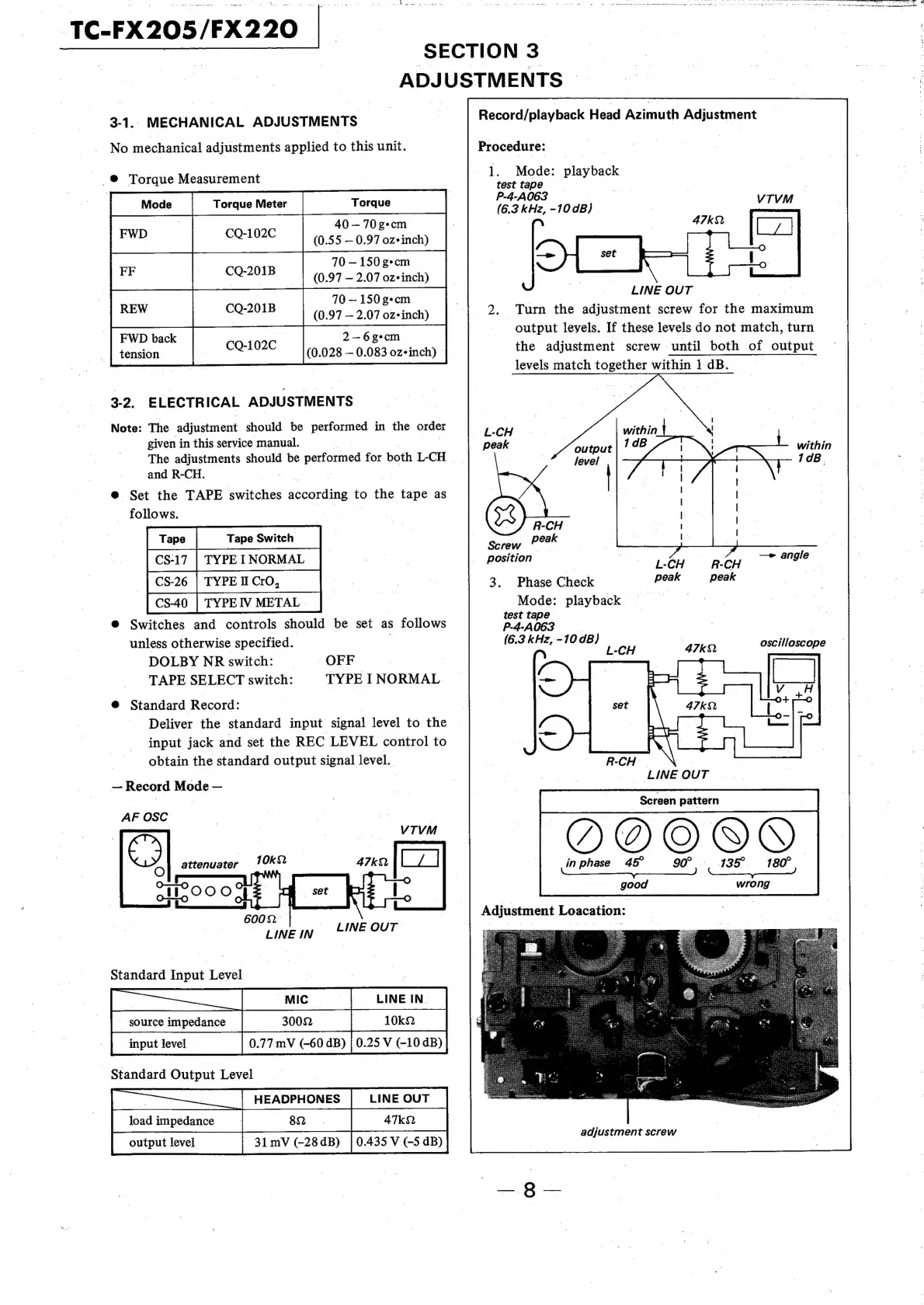
Record/playback
Head
Azimuth
Adjustment
Procedure:
1.
Mode:
playback
test
tape
P-4-A063
(6.3
kHz,
-10
dB)
LINE
OUT
|
s
2.
Turn
the
adjustment
screw
for
the
maximum
output
leyels.
If
these
levels
do
not
match,
turn
the
adjustment
screw
until
both
of
output
levels
match
together
within
1
dB.
peak
|
within
| |
70B
|
R-CH
peak
Screw
Ate
:
Position
-
eae
pie
—e
angle
3.
Phase
Check
peak
peak
Mode:
playback
test
tape
|
P-4-A063
(6.3
kHz,
-10
dB)
L-CH
RCH
N
|
~
LINE
OUT
|
Screen
pattern
Y)
©)
in
phase
45°
90°.
135°.
=:
180°
ees
wrong
good
Adjustment
Loacation:
adjustment
screw