Do you have a question about the Sony TC-K990ES and is the answer not in the manual?
Guidelines and precautions for repairing flexible circuit boards.
How to verify and set the unit's operating voltage.
Step-by-step guide to bias and recording level calibration.
Step-by-step guide for adjusting bias and recording level.
Instructions for calibrating recording equalization for different sound profiles.
Details the Dolby HX PRO system for enhanced recording quality.
Safety notes and definitions for mechanical adjustments.
Guide for aligning tape path and adjusting heads.
Fine-tuning head declination, azimuth, and depth for tape path.
Steps for adjusting the erasehead's azimuth and height.
Adjusting head depth, pinch roller force, and torque specifications.
Setup for electrical calibration and general notes.
Setting standard levels and adjusting head azimuth.
Verifying phase and adjusting bias oscillator frequency.
Calibrating bias current and record levels for CrO2 tapes.
Procedures for adjusting bias on metal and normal tapes.
Calibrating meter levels and oscillator settings.
| Track System | 4-track, 2-channel stereo |
|---|---|
| Tape Speed | 4.76 cm/s |
| Motor | DC Servo Motor |
| Wow and Flutter | 0.04% WRMS |
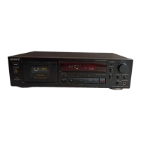
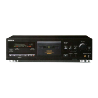
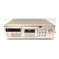
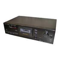
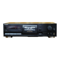
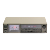
| Type | Stereo Cassette Deck |
| Heads | 2 x Playback, 1 x Record, 1 x Erase |
| Tape Types Supported | Type I (Normal), Type II (Chrome), Type IV (Metal) |
| Frequency Response | 20 Hz to 20 kHz |
| Input | Line Level |
| Output | Line Level |
| Inputs | Line In |
| Outputs | Line Out (RCA), Headphones |