3
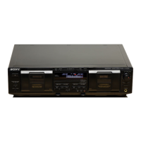
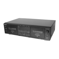
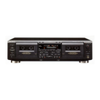
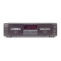
TC-WE475
PARTS No. MODEL
4-232-514-0s US model
4-232-514-1s CND model
4-232-514-2s AEP model
4-232-514-3s UK model
4-232-514-4s SP model
4-232-514-5s AUS model
MODEL IDENTIFICATION
–Back panel–
Part No.
• Abbreviation
CND : Canadian model
SP : Singapore model
AUS : Australian model
TABLE OF CONTENTS
1. GENERAL .......................................................................... 4
2. DISASSEMBLY
2-1. Case ...................................................................................... 5
2-2. Front Panel Assy ................................................................... 5
2-3. Cassette Lid Assy (Deck A/B) .............................................. 6
2-4. Mechanism Deck Assy (Deck A/B) ...................................... 6
3. SERVICE MODE .............................................................. 7
4. MECHANICAL ADJUSTMENTS ................................. 8
5. ELECTRICAL ADJUSTMENTS ................................. 8
6. DIAGRAMS
6-1. Circuit Boards Location ...................................................... 12
6-2. Printed Wiring Board – MAIN Section –............................ 14
6-3. Schematic Diagram – MAIN (1/4) Section –...................... 15
6-4. Schematic Diagram – MAIN (2/4) Section –...................... 16
6-5. Schematic Diagram – MAIN (3/4) Section –...................... 17
6-6. Schematic Diagram – MAIN (4/4) Section –...................... 18
6-7. Printed Wiring Board – DECK A Section – ........................ 19
6-8. Schematic Diagram – DECK A Section –........................... 19
6-9. Printed Wiring Board – DECK B Section –........................ 19
6-10. Schematic Diagram – DECK B Section –......................... 19
6-11. Schematic Diagram – DISPLAY Section –....................... 20
6-12. Printed Wiring Board – DISPLAY Section – .................... 21
6-13. Schematic Diagram – PANEL Section –........................... 22
6-14. Printed Wiring Board – PANEL Section – ........................ 23
6-15. Schematic Diagram – POWER Section – ......................... 24
6-16. Printed Wiring Board – POWER Section – ...................... 25
6-17. IC PIN FUNCTION .......................................................... 26
7. EXPLODED VIEWS
7-1. Case Section........................................................................ 27
7-2. Chassis Section ................................................................... 28
7-3. Cassette Holder Section ...................................................... 29
7-4. Front Panel Section ............................................................. 30
7-5. Tape Mechanism Section .................................................... 31
8. ELECTRICAL PARTS LIST ........................................ 32