9
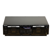
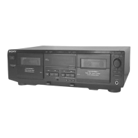
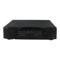
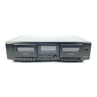
TC-WE475
Record/Playback Head Azimuth Adjustment
DECK A DECK B
Procedure:
1. Forward Playback Mode
2. Turn the adjustment screw for the maximum output levels. If
these levels do not match, turn the adjustment screw until both
of output levels match together within 1 dB.
3. Playback Mode
4. Change the reverse playback mode and repeat the steps 1 to 3.
5. After the adjustment, lock the adjustment screws with suitable
locking compound.
Adjustment Location: – record/playback head –
Tape speed Adjustment DECK A DECK B
Adjust DECK A first
Procedure:
– Forward Playback Mode –
(High speed adjustment)
1. Press the PITCH CONTROL button to set to OFF .
2. Set to test mode. (Refer to page 11.)
3. Press the H button to playback.
4. Press the HIGH/NORMAL button to playback at double speed.
5. Adjust RV316 (DECK A), RV416 (DECK B) so that the fre-
quency counter reading becomes 5,980 ± 180 Hz.
(Normal speed adjustment)
6. Press the H button to playback.
7. Press the HIGH/NORMAL button to playback at normal speed.
8. Adjust RV317 (DECK A), RV417 (DECK B) so that the fre-
quency counter reading becomes 3,000 ± 90 Hz.
(Pitch control adjustment) (DECK A)
9. Press the PITCH CONTROL button to set to ON .
10. Set PITCH CONTROL knob to mechanical center.
11. Press the H button to playback.
12. Adjust RV318 so that the frequency counter reading becomes
2,990 ± 90 Hz.
Adjustment Location: MAIN board (See page 14.)
Sample value of wow and flutter
W.RMS (JIS) less than 0.3% .
(test tape : WS-48B)
Playback Level Adjustment DECK A DECK B
Procedure:
– Forward Playback Mode –
Adjust DECK A : RV111 (L-CH), RV211 (R-CH) and
DECK B : RV121 (L-CH), RV221 (R-CH) so the level meter read-
ing becomes the adjustment limits below.
Adjustment Value:
LINE OUT level : –7.7 dBs ± 0.5 dB (0.301 to 0.338 V)
Level difference between channels : within 0.5 dB
Confirm that the LINE OUT level does not change in playback mode
while changing the mode from playback to stop several times.
Adjustment Location: MAIN board (See page 14.)
set
test tape
P-4-A100
(10 kHz, –10 dB)
level mete
 Loading...