7
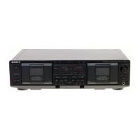
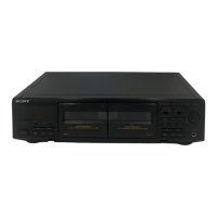
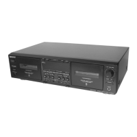
TC-WE675
RESET 0
MEMORY 1
RMS/START 2
SET 3
CHECK 4
DISPLAY 5
m (AMS) 6
(AMS) M 7
x/CLEAR Grid check display (*1)
n/BACK 8
N/FRONT 9
PAUSE X A
REC MUTING W b
REC z C
DIRECTION MODE switch
g h
s PLAY
RELAY H
A deck side
Button Display
KEY CHECK & DISPLAY CHECK MODE
While pressing the h/BACK (A deck) and REC MUTING W (B deck) buttons with the power off, press the POWER button to turn on
the power.
The fluorescent display tube displays the number or special message corresponding to the button pressed.
The message displayed differs according to the position of the switch.
SECTION 3
SERVICE MODE
RESET 0
MEMORY 1
DECK A 2
DECK B 3
A+B REC 4
HIGH/NOMAL 5
m (AMS) 6
(AMS) M 7
x Segment check display (*2)
h 8
H 9
PAUSE X A
REC MUTING W b
REC z C
FADER d
ARL E
SYNCHRO All lit
DOLBY NR switch (*3)
OFF h
B PLAY
C H
B deck side
Button Display
Grit check display (*1)
Segment check display (*2)
RMS
(*3) The DOLBY NR switch consists of a pair of switches.
B and C are valid only in the ON or ON FILTER state.
 Loading...