– 2 –
In this set, the S102 (power) detects REC/PLAYBACK on.
It is mounted on the MAIN board, and therefore the REC/PLAY-
BACK on cannot be detected with the MAIN board removed.
When making an operation check and voltage check of mechani-
cal deck with the MAIN board removed, fix the S102 at turn on.
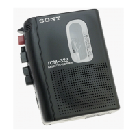
SECTION 1
SERVICING NOTES
Notes on chip component replacement
• Never reuse a disconnected chip component.
• Notice that the minus side of a tantalum capacitor may be dam-
aged by heat.
[MAIN BOARD] (Conductor Side)
IC101
IC102
IC601
TABLE OF CONTENTS
1. SERVICING NOTES ............................................... 2
2. GENERAL .................................................................. 3
3. DISASSEMBLY ......................................................... 4
4. MECHANICAL ADJUSTMENTS ....................... 7
5. ELECTRICAL ADJUSTMENTS......................... 8
6. DIAGRAMS
6-1. Block Diagram ................................................................ 9
6-2. Schematic Diagram ......................................................... 11
6-3. Printed Wiring Board ...................................................... 13
7. EXPLODED VIEWS ................................................ 14
8. ELECTRICAL PARTS LIST ............................... 17
 Loading...