1-14
BVM-D9H1U/D9H5U/D9H1E/D9H5E/D9H1A/D9H5A
22
(E)
Chapter 1 Overview
Location and Function of Parts
1 PARALLEL REMOTE1/2 connectors
(1: female, D-sub 9-pin, 2: modular connector)
Form a parallel switch and controls the monitor
externally. The pin assignment and factory setting
function assigned to each pin are given below.
1: D-sub 9-pin
All pin function assignments can be changed with the
REMOTE menu.
For information about the REMOTE menu, see “ [D]
Assigning the Remote Control Functions — REMOTE
Menu” on page 37(E).
Pin number
1
Set input signal channel 1 (numeric keypad
function)
2
Set input signal channel 2 (numeric keypad
function)
3 Set red tally lamp on or off
4 Set green tally lamp on or off
5 Select sync signal (SYNC button function)
6 Set underscan on or off
7 Set a 16:9 aspect ratio on or off
8
Functions
Set the 4:3 area marker display on or off
9
GND
Pin number
1
Set input signal channel 1 (numeric keypad
function)
2
Set input signal channel 2 (numeric keypad
function)
3 Set red tally lamp on or off
4 Set green tally lamp on or off
5 GND
6 Set underscan on or off
Functions
Cable with D-sub 9-pin plugs
(not supplied)
Monitor 1 Monitor 2
IN
SERIAL
REMOTE
SERIAL
REMOTE
OUT
IN
OUT
To switch each function between on and off or
between enable and disable, change pin connections in
the following way.
ON or enabled: Short each pin and pin 9 together for
D-sub 9-pin.
Short each pin and pin 5 together for modular
connector.
OFF or disabled: Leave each pin open.
2 SERIAL REMOTE connectors
(female, D-sub 9-pin)
These are RS-485 serial interface connectors, used for
connecting two or more BVM-xxE/F/G, BVM-xxD
and HDM-xxE series monitors.
The IN and OUT connectors form a loop-through
connection.
Connect two monitors using a cable with D-sub 9-pin
plugs such as an RCC-5G (not supplied) as shown in
the figure on the next page.
3 Input option slots (three slots)
The monitor may be fitted with optional input adaptors
up to three.
The BKM-129X is installed to the monitor at the
factory.
Notes
•The BKM-142HD uses two input option slots.
•Each adaptor can also be installed into SLOT 1.
Install any adaptor to SLOT 1.
23
(E)
Chapter 1 Overview
6 AC IN connector (3-pin)
Connects the monitor to an AC power source, via the
supplied AC power cord.
7 CONTROL UNIT connector (female, D-sub 9-
pin) (BVM-D14H1U/D14H1E/D14H1A only)
Connects a monitor control unit such as the BKM-10R
using a cable with D-sub 9-pin plugs such as an RCC-
5G (not supplied).
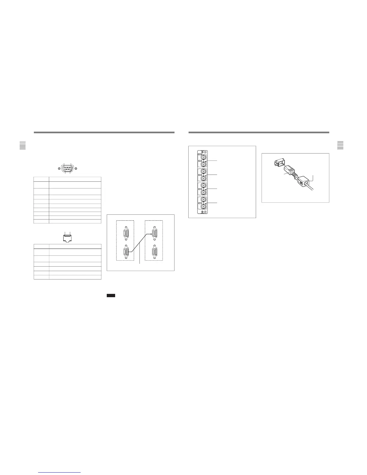
4 Analog input/output connectors (BKM-129X)
RGB signals or component signals (Y/P
B/PR) can be
fed in the IN connectors. The type of signal applied to
each connector is set with the INPUT CONFIG menu.
The OUT connectors are used for loop-through output
of the input signal.
For information about the INPUT CONFIG menu, see “ [C]
Setting the Input Configuration — INPUT CONFIG Menu”
on page 35(E).
5 MAIN POWER switch
When turned on, the monitor enters operation mode.
By setting in the SYSTEM CONFIG menu, the
monitor can also be set to enter standby mode when
the MAIN POWER switch is turned on.
For information about the SYSTEM CONFIG menu, see “
[E] Setting the Power-Up Conditions and Data about the
Screen Display — SYSTEM CONFIG Menu” on page 39(E).
Attach the AC plug holder to the AC power cord, and
connect it to the AC IN connector so that the cord does not
come loose.
AC plug holder (supplied)
AC power cord
(supplied)
Y/G connectors (BNC)
P
B
/B connectors (BNC)
P
R
/R connectors (BNC)
SYNC connectors (BNC)
129X
IN
OUT
IN
OUT
IN
OUT
IN
OUT
ANALOG
Y/G
P
B
/B
P
R
/R
SYNC