3-10
BVM-D9H1U/D9H5U/D9H1E/D9H5E/D9H1A/D9H5A
[G2 Adjustment]
1. Turn off the POWER switch.
2. Disconnect the connector CN701 from the C board.
3. Apply the following DC voltage to pin-1, pin-3 and
pin-5 of CN701 on the C board respectively.
100 ±2 V
4. Turn on the POWER switch.
5. Adjust the SCREEN control of FBT to the point of
immediately before the blanking lines disappear on
screen.
6. Turn off the POWER switch.
7. Remove the DC voltages that are applied in step 3,
from the C board
8. Re-connect the connector CN701 to the C board.
[White Balance Adjustment]
1. Outline of the white balance adjustment and calibra-
tion of the color analyzer that is used for the white
balance adjustment are described first.
1.1 The parameter that converts the RGB drive voltage of
a CRT to the chromaticity coordinate is acquired.
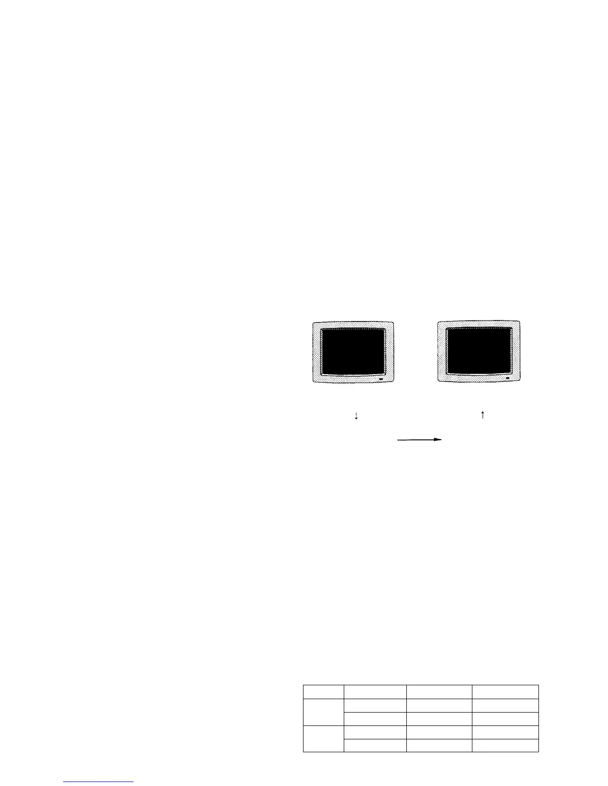
This monitor has the copy function of the color temperature
data between two or more monitors.
However, the CRT drive voltage are unique in every
monitor because it is different depending on each CRT.
Therefore, the same color temperature cannot be obtained in
multiple monitors even though the same drive voltage is
given to them. It means that the data that is used to copy the
color temperature, must be the xyY chromaticity coordinate
or similar data that does not depend on each CRT, unlike the
CRT drive that depends on each CRT.
When the D93 MANUAL adjustment is implemented using
the MAINTENANCE/SYSTEM/COLOR TEMP menu of
the SYSTEM CONFIG menu, the parameter that converts
the CRT drive voltage to the chromaticity coordinate is
created while the adjustment is implemented. This parame-
ter is used when copying the color temperature data to other
monitors as shown.
Fig. 1-15
1.2 D65 color temperature adjustment
1.3 Copying the color temperature data to the STD color
temperature, COLOR1 color temperature and COL-
OR2 color temperature.
..
..
. On calibration of the color analyzer
When color temperature of any monitor is measured by
two or more color analyzers, these color analyzers show
different measurement values even though the object of
measurement is the same. Also the measurement value
of color analyzer changes as time elapses.
Therefore, any color analyzer must be calibrated so that
it shows the correct measurement value of the following
chromaticity coordinate before using the analyzer.
CRT drive voltage
CRT drive voltage
Chromaticity coordinate Chromaticity coordinate
Data transmission
x y y (cd/m
2
)
D65 0.313 0.329 2.7
0.313 0.329 120
D93 0.283 0.297 2.7
0.283 0.297 120