3-5
BVM-D9H1U/D9H5U/D9H1E/D9H5E/D9H1A/D9H5A
..
..
. H. Blanking Adjustment
1. Press the SHIFT button to ON. [The LED (orange) on
top of the button turns on.]
2. To select the 4:3 mode of the adjustment, press the
16:9 OFF button [to turn off the LED (orange)] to
select the 4:3 mode.
To select the 16:9 mode of the adjustment, press the
16:9 ON button [to turn on the LED (orange)] to select
the 16:9 mode.
3. Press the SHIFT button to OFF. [The LED (orange)
on top of the button turns off.]
4. To select the NORMAL mode of adjustment, press the
UNDER SCAN button ( ) to its OFF position to
select the normal mode. [The green LED turns off.]
To select the UNDER SCAN mode of adjustment,
press the UNDER SCAN button ( ) to its ON
position to select the under scan mode. [The green
LED turns on.]
5. Set the following data to maximum.
H BLK LEFT : 255
H BLK RIGHT : 255
6. Adjust the H. SIZE data so that the entire raster area is
visible on screen.
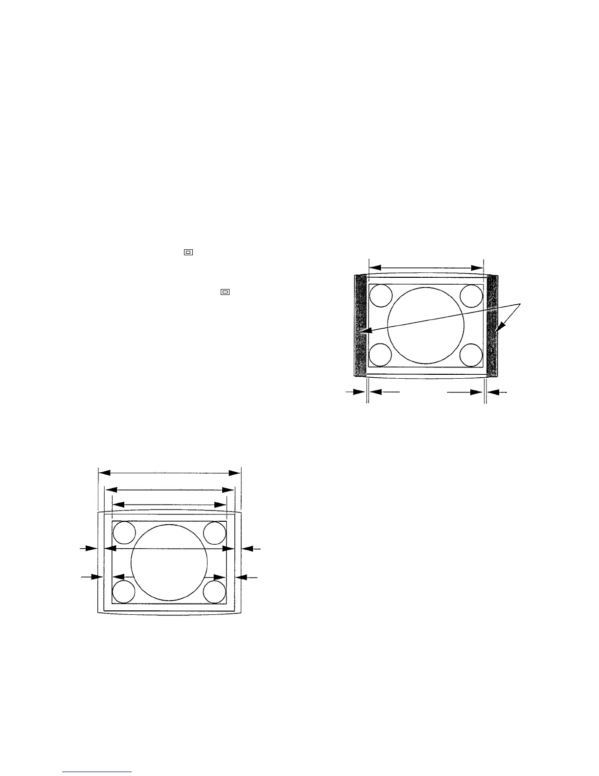
7. Adjust the H. CENTER data so that the raster is
position just in the center of the screen (so that A = B).
(Fig. 1-5)
Fig. 1-5
Effective screen area
Deflection area (raster area)
Signal display area
A
C
B
D
H CENTER
A=B
H PHASE
C=D
8. Adjust the H. PHASE data so that the monoscope
picture is position just in the center of the raster (so
that C = D).
9. Adjust the H. BLK. RIGHT data so that the horizontal
blanking is position 0 to 2 mm outside the right end of
the monoscope signal display area. (Fig. 1-6)
10. Adjust the H. BLK. LEFT data so that the horizontal
blanking is position 0 to 2 mm outside the left end of
the monoscope signal display area. (Fig. 1-6)
11. Return the H. SIZE data to the original data size.
Fig. 1-6
Signal display area
H BLK WIDTH H BLK PHASE
2 to 3 mm
H BLK