3-7
BVM-D9H1U/D9H5U/D9H1E/D9H5E/D9H1A/D9H5A
. Linearity Adjustment (2)
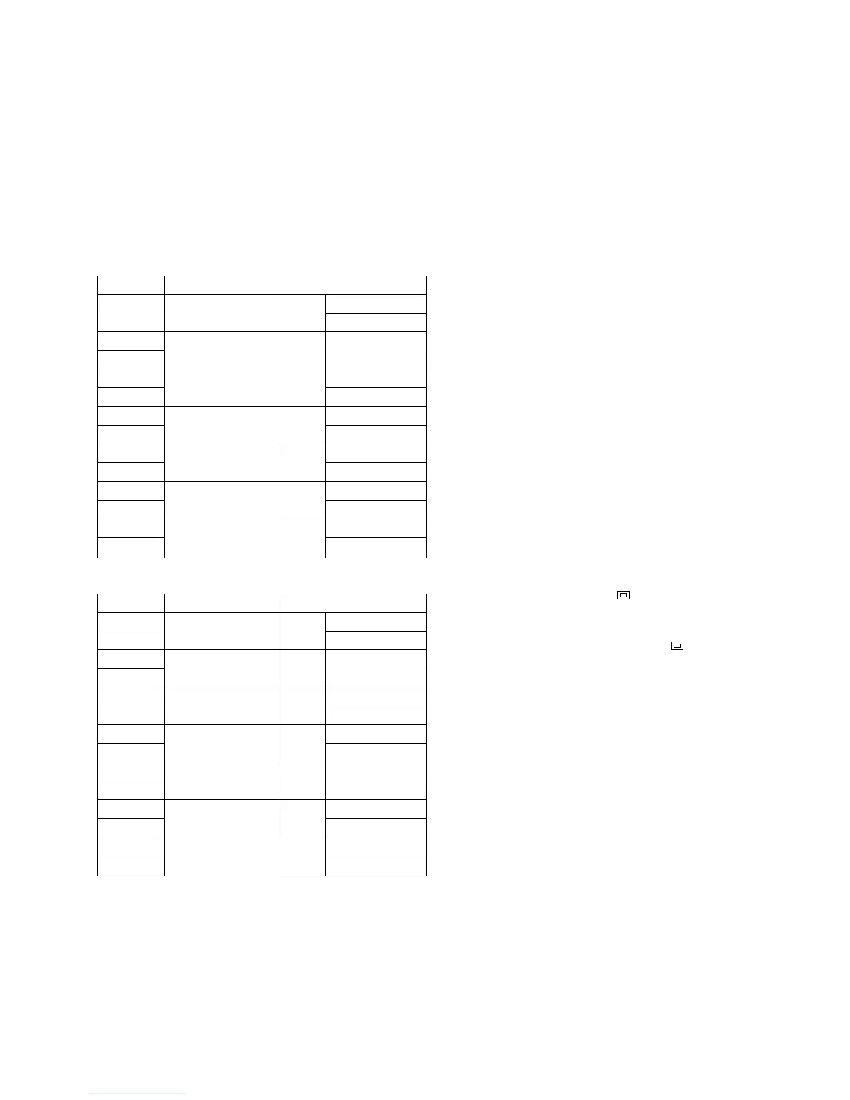
Note 1)Connect the monoscope signal or the cross-hatch
signal having the following signal formats as
shown in the table below, to the ANALOG Y/G
input connector. Perform the linearity adjustment
(2) in the respective screen modes using the
respective signal formats.
60 Hz system
50 Hz system
MODE
MODE1
MODE2
MODE3
MODE4
MODE5
MODE6
MODE7
MODE8
MODE9
MODE10
MODE11
MODE12
MODE13
MODE14
Signal format
1080/60i 16 : 9
(1125)
1035/60i 16 : 9
(1125)
720/60p 16 : 9
480/60p 16 : 9
(525)
4 : 3
480/60i 16 : 9
(525)
4 : 3
Screen mode
NORMAL
UNDER SCAN
NORMAL
UNDER SCAN
NORMAL
UNDER SCAN
NORMAL
UNDER SCAN
NORMAL
UNDER SCAN
NORMAL
UNDER SCAN
NORMAL
UNDER SCAN
MODE
MODE15
MODE16
MODE17
MODE18
MODE19
MODE20
MODE21
MODE22
MODE23
MODE24
MODE25
MODE26
MODE27
MODE28
Signal format
1080/48i 16 : 9
(1125)
1080/50i 16 : 9
(1125)
720/50p 16 : 9
575/50P 16 : 9
(625)
4 : 3
575/50i 16 : 9
(625)
4 : 3
Screen mode
NORMAL
UNDER SCAN
NORMAL
UNDER SCAN
NORMAL
UNDER SCAN
NORMAL
UNDER SCAN
NORMAL
UNDER SCAN
NORMAL
UNDER SCAN
NORMAL
UNDER SCAN
Note 2)The following adjustment menus are located in the
directory under the DEFLECTION menu of the
MAINTENANCE menu.
H SIZE
H CENTER
H KEY BAL
H KEY
H PIN BAL
H PIN
H COR S
H COR PIN
H PIN
V SIZE
V CENTER
V LIN AMP
V LIN BAL
1. Connect the monoscope signal to the ANALOG Y/G
input connector.
2. Press the SHIFT button to ON. [The LED (orange) on
top of the button turns on.]
3. To adjust the 4:3 mode of adjustment, press the 16:9
OFF button [to turn off the LED (orange)] to select the
4:3 mode.
4. Press the SHIFT button to OFF. [The LED (orange)
on top of the button turns off.]
5. To select the NORMAL mode of adjustment, press the
UNDER SCAN button ( ) to its OFF position to
select the normal mode. [The green LED turns off.]
To select the UNDER SCAN mode of adjustment,
press the UNDER SCAN button ( ) to its ON
position to select the under scan mode. [The green
LED turns on.]
6. Adjust the H CENTER data so that the horizontal
center of the picture comes to the horizontal center of
the screen.
7. Adjust the V CENTER data so that the vertical center of the
picture comes to the vertical center of the screen.
8. Connect the cross-hatch signal to the ANALOG Y/G
input connector.
9. Adjust the respective V SIZE, V LIN BAL, V LIN
AMP and H SIZE data so that the optimum picture is
obtained as shown in Fig. 1-8.
Note: Do not adjust the V SIZE data when adjusting the
MODEs 9, 13, 23 and 27.
10. Adjust the trapezoidal distortion and PIN distortion on
both sides of picture using the H KEY BAL, H KEY,
H PIN BAL and H PIN data respectively as shown in
Fig. 1-9.
11. Adjust the corner “S” distortion and the corner PIN
distortion on both sides of picture using the H CORS and
H COR PIN data respectively as shown in Fig. 1-10.
12. Repeat the above-described steps of the linearity
adjustment(2) until the optimum horizontal linearity
and vertical linearity are obtained.