5-2
BVM-D9H1U/D9H5U/D9H1E/D9H5E/D9H1A/D9H5A
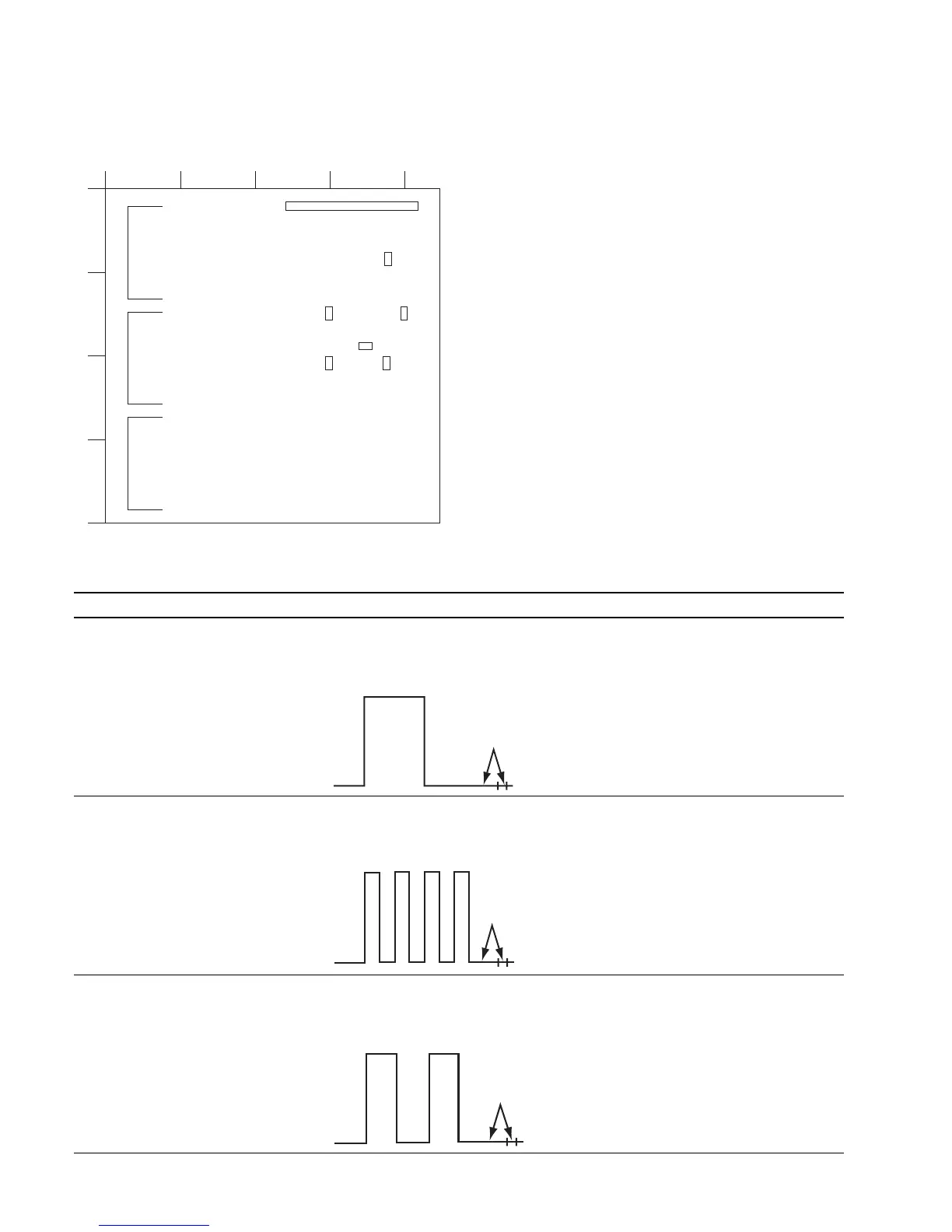
Connection (2)
B Board -side A-
12345
A
B
C
D
TP1301
TP304 TP303
TP1300 TP1302
TP302
CN301
IC2345IC2355IC2365
Adjustment Procedure
1. RGB Signal Adjustment
Status During Adjustment Specifications Adjustment Point
Step 1 Adjust the GREEN waveforms to have Use the adjustment menu Y/G BLACK
..
..
. Input the 15 kHz/60 Hz the same amplitude at TP302. (40H) that is located under the directory
RGB 100% color bar signal. Level difference: 0 ±10 mV of the VIDEO menu of the
..
..
. Use the FORMAT item of the MAINTENANCE menu.
INPUT CONFIG menu to select RGB.
..
..
. Connect an oscilloscope to TP302.
Step 2 Make flat the pedestal portion of the Use the adjustment menu PB/B BLACK
..
..
. Connect an oscilloscope to TP303. BLUE waveform at TP303. (30H) that is located under the directory
Level difference: 0 ±10 mV of the VIDEO menu of the
MAINTENANCE menu.
Step 3 Make flat the pedestal portion of the Use the adjustment menu PR/R BLACK
..
..
. Connect an oscilloscope to TP304. RED waveform at TP304. (20H) that is located under the directory
Level difference: 0 ±10 mV of the VIDEO menu of the
MAINTENANCE menu.
Make flat
Make flat
Make flat