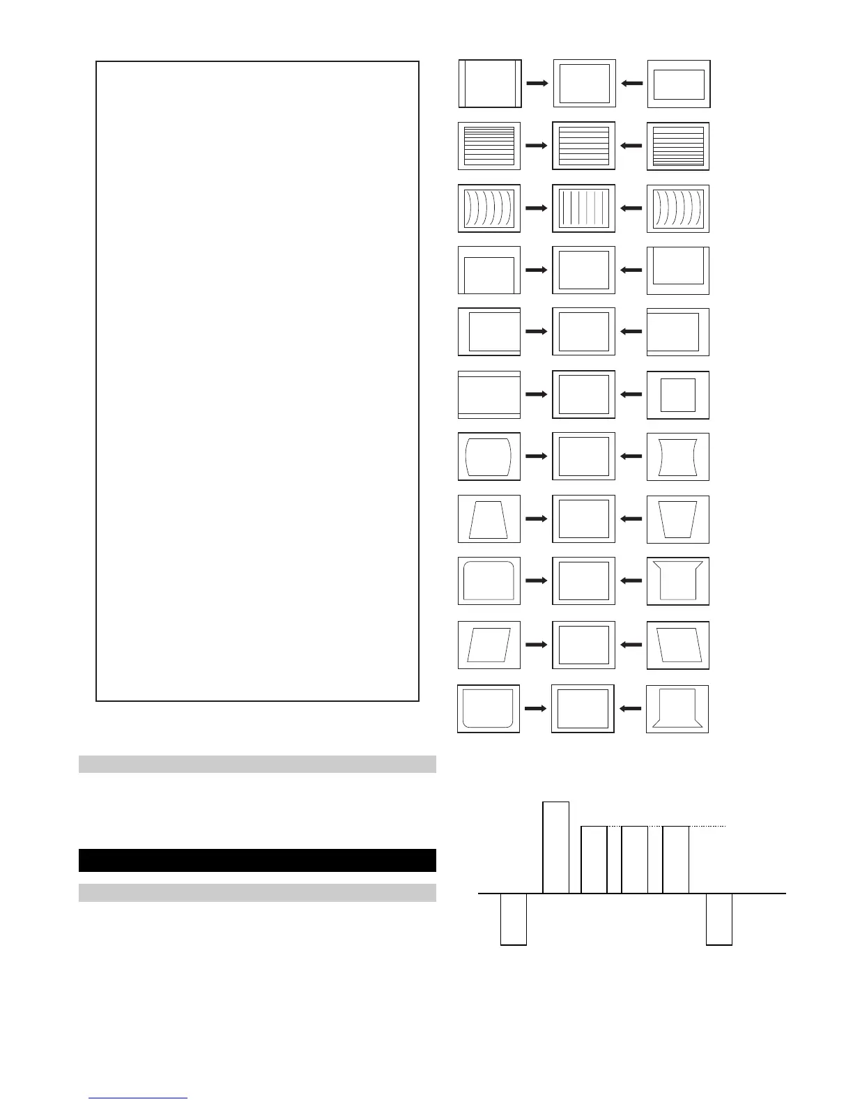
27
V SIZE
V LIN
AFC V BOW
V POS
H POS
H SIZE
H PIN CUSH
H TILT
H UP COR
AFC V ANGLE
H LOWER COR
Same Level
B-Out Waveform
Table.4-13
1. Enter into the service mode and select ‘Deflection’ from the
menu. The ‘Deflection’ adjustment menu will be displayed.
2. Select and adjust each item to obtain the optimum image.
4-2. Volume Electrical Adjustments
Deflection System Adjustment
Sub Colour Adjustment
1. Input a PAL colour bar signal.
2. Connect an oscilloscope to CN5400 pin 5 located on the C Board.
3. Enter into the ‘Service Mode’.
4. Choose ‘Backend’ from the menu.
5. Adjust ‘Sub Colour’ data so that the right sides of the waveform
are of equal height.
noitcelfeD
oNrcseDfeDniMxaMataD
1eziS-V1303622
2noitisoP-V1303633
3pmoC-V1031
4raeniL-V70517
5rroC-S70517
6eziS-H1303673
7CD-WEFFOFFONOFFO
82miTbkAFFOFFONOFFO
9pmA-niP1303604
01pmoC-H0030
11nipC-pU1303633
21niP-M2032
31niPC-oL1303623
41muizeparT70517
51noitisoP-H1303682
61wKlbV0030
71woB-CFA70517
81elgnA-CFA70517
91klB-tfeL2503625
02klB-thgiR110 3611
12nureerF-V0030
22tcepsA-V00360
32wS-mooZFFOFFONOFFO
42nacS-UFFOFFONOFFO
52llorcS-V1303613
62miT-bkA2032
72nilV-pU00510
82nilV-oL00510
92pmAPPIPM5-01-01+5-
03niPCUPIPM001-01+0
13niPCLPIPM001-01+0
23parTPIPM001-01+0
33pmAPGPE3-01-01+3-
43niPCUGPE001-01+0
53niPCLGPE101-01+1
63parTGPE001-01+0




 To Next Page