EasyManua.ls Logo

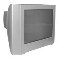
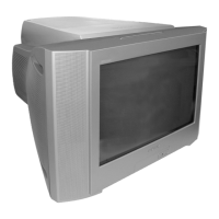
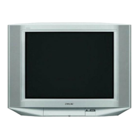
Sony TRINITRON KV-HW21M80 User Manual

Sony TRINITRON KV-HW21M80
116 pages
To Next Page IconTo Next Page
Page #1 background imageLoading...
Page #1 background image
REVISION HISTORY
BX1
MODEL
KV-HW21M80
KV-HW21M83
KV-HW21M80J
PA RT N O. : 9-872-408-01
CHASSIS
NO. SUFFIX DATE SUPP / CORR DESCRIPTION
1 -01 2003/11 _ _ 1st Issue

Table of Contents

Questions and Answers:

Sony TRINITRON KV-HW21M80 Specifications

General IconGeneral
Screen Size21 inches
Display TechnologyCRT
BrandSony
ModelKV-HW21M80
Aspect Ratio4:3
ResolutionStandard Definition
InputsComposite

Summary

REVISION HISTORY

MODEL

Lists the specific TV models covered by the revision history.

PART NO.

Specifies the part number associated with the revision history.

SELF DIAGNOSTIC FUNCTION

1. DIAGNOSTIC TEST INDICATORS

Describes diagnostic test indicators for TV self-diagnosis function.

2. DISPLAY OF STANDBY ( ) INDICATOR FLASH COUNT

Explains how to interpret the flashing STANDBY indicator for error codes.

3. STOPPING THE STANDBY ( ) INDICATOR FLASH

Details the procedure to stop the flashing STANDBY indicator.

4. SELF-DIAGNOSTIC SCREEN DISPLAY

Explains how to display self-diagnosis results on the screen.

5. HANDLING OF SELF-DIAGNOSTIC SCREEN DISPLAY

Provides instructions for clearing and managing self-diagnosis screen data.

6. SELF-DIAGNOSTIC CIRCUIT

Illustrates the circuit diagram for the self-diagnosis function.

SECTION 1 DISASSEMBLY

1-1. 3D SPEAKER REMOVAL

Procedure for removing the 3D speaker assembly from the TV.

1-2. REAR COVER REMOVAL

Instructions on how to remove the rear cover of the TV.

1-3. SPEAKER REMOVAL

Steps for removing the main speaker unit.

1-4. CHASSIS ASSY REMOVAL

Guide for removing the entire chassis assembly from the TV.

1-5. SERVICE POSITION

Describes the recommended position for servicing the TV.

1-6. TERMINAL BRACKET REMOVAL

Instructions for removing the terminal bracket.

1-7. J BOARD REMOVAL

Procedure for removing the J board.

1-8. A BOARD REMOVAL

Steps for removing the A board.

1-9. PICTURE TUBE REMOVAL

Guide for safely removing the picture tube.

SECTION 2 SET-UP ADJUSTMENTS

2-1. BEAM LANDING

Procedure for adjusting beam landing for optimal picture alignment.

2-2. CONVERGENCE

Instructions for adjusting screen convergence for color alignment.

2-3. FOCUS ADJUSTMENT

Steps for adjusting the focus for sharp picture clarity.

2-4. G2 (SCREEN) ADJUSTMENT

Guide for adjusting the G2 (screen) voltage on the FBT.

2-5. WHITE BALANCE ADJUSTMENT

Procedure for adjusting white balance for accurate color reproduction.

2-6. SUB BRIGHT ADJUSTMENT

Steps for adjusting sub-brightness for proper picture contrast.

SECTION 3 CIRCUIT ADJUSTMENTS

3-1. ADJUSTMENT WITH COMMANDER

Details service adjustments using the RM-W101 remote control.

3-2. ADJUSTMENT METHOD

Explains the general method for performing service adjustments.

3-3. PICTURE QUALITY ADJUSTMENTS

Instructions for adjusting various picture quality parameters.

3-4. DEFLECTION ADJUSTMENT

Guide for adjusting deflection parameters for picture geometry.

3-5. DRIVE ADJUSTMENT

Steps for adjusting drive signals for optimal TV performance.

3-6. PICTURE DISTORTION ADJUSTMENT

Procedure for correcting various picture distortions.

SECTION 4 DIAGRAMS

4-1. BLOCK DIAGRAM

Overall block diagram of the TV's internal circuitry.

4-2. CIRCUIT BOARDS LOCATION

Diagram showing the physical location of main circuit boards.

4-3. SCHEMATIC DIAGRAM INFORMATION

Provides general information and reference for schematic diagrams.

4-3-1. C BOARD SCHEMATIC DIAGRAM

Schematic diagram for the C board (Video Amp).

4-3-2. A BOARD — PROCESSOR (BLOCK A)

Schematic diagram of the A board's processor section.

4-3-3. A BOARD — AUDIO (BLOCK B)

Schematic diagram of the A board's audio processing section.

4-3-4. A BOARD — POWER SUPPLY (BLOCK C)

Schematic diagram of the A board's power supply section.

4-3-5. A BOARD — DEFLECTION (BLOCK D)

Schematic diagram of the A board's deflection circuit.

4-3-6. A BOARD — TUNER (BLOCK E)

Schematic diagram of the A board's tuner section.

4-3-7. A BOARD — JACK (BLOCK F)

Schematic diagram of the A board's input/output jack section.

4-3-8. J BOARD SCHEMATIC DIAGRAMS

Schematic diagram for the J board (3D Terminal).

4-4. VOLTAGE MEASUREMENT AND WAVEFORMS

Lists expected voltages and waveforms for testing.

4-5. PRINTED WIRING BOARDS AND PARTS LOCATION

Illustrates the layout of printed circuit boards and component placement.

4-6. SEMICONDUCTORS

Illustrations and identification of common semiconductor components.

SECTION 5 EXPLODED VIEWS

5-1. CHASSIS

Exploded view of the TV chassis and its main components.

SECTION 6 ELECTRICAL PARTS LIST

CAPACITOR

List of capacitors used in the TV with part numbers and specifications.

COMMON PARTS LIST

List of commonly used parts across different models.

CONNECTOR

List of connectors used in the TV with part numbers.

DIODE

List of diodes used in the TV with part numbers and types.

IC

List of integrated circuits used in the TV with part numbers.

TRANSISTOR

List of transistors used in the TV with part numbers and types.

WARNING

Securing the TV

Installation

Getting Started

Steps for initial remote setup and basic connections.

Setting up your TV (“Initial Setup”)

Guide for configuring TV language, channels, and position.

Overview of Controls

TV top control, front and rear panels

Diagrams showing the location and function of TV controls.

Using the remote control and basic functions

Instructions on operating the TV using the remote control.

Advanced Operations

Selecting the picture and sound modes

How to choose and adjust picture and sound presets.

Viewing Teletext (KV-HW21M85/HW21M81 only)

Guide to accessing and using Teletext features.

Menu Adjustment

Introducing the menu system

Overview of the TV's menu structure and navigation.

Changing the “Picture” setting

Instructions for adjusting picture parameters like mode and color.

Changing the “Sound” setting

Steps for adjusting sound parameters like mode and balance.

Adjusting the “Sound Adjustment” item under “Personal” mode

Guide to fine-tuning sound frequencies in Personal mode.

Changing the “Timer” setting

Instructions for setting sleep and wake-up timers.

Changing the “Channel Setup” setting

Steps for managing TV channels, including auto-program and blocking.

Presetting channels manually

Guide for manually tuning and storing TV channels.

Changing the “Setup” setting

Instructions for changing language, picture rotation, and color system.

Additional Information

Connecting optional components

Instructions for connecting external devices like VCRs and audio systems.

Connecting to the video input terminal

Guide for connecting video sources to the TV's input terminals.

Connecting to the component video input terminal

Instructions for connecting component video sources.

Connecting to the monitor output terminal

Guide for connecting the TV to external monitors or audio systems.

Troubleshooting

Guide to diagnosing and resolving common TV problems.

Specifications

Related product manuals