– 57 –
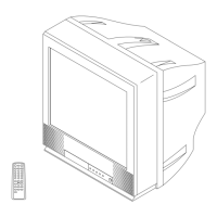
KV-PF21N70/PF51P40/PF21P70/PF21Q40
RM-915 RM-952 RM-952 RM-952
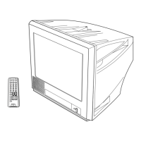
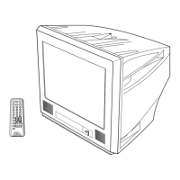
KV-PF21Q70/PF21M70/PF21DK7
RM-952 RM-952 RM-952
5-4. SCHEMATIC DIAGRAMS AND PRINTED WIRING BOARDS
Note:
• All capacitors are in µF unless otherwise noted.
• All electrolytic capacitors are rated at 50V unless otherwise noted.
• All resistors are in ohms.
k = 1000 , M = 1000k
• Indication of resistance which does not have rating electrical
power is as follows.
Pitch: 5 mm
Rating electrical power 1/4W (CHIP: 1/10W)
• : nonflammable resistor.
• ¢ : internal component.
• : panel designation or adjustment for repair.
• All variable and adjustable resistors have characteristic curve B
unless otherwise noted.
• Readings are taken with a color-bar signal input.
no mark : PAL
( ) : SECAM
[ ] : NTSC 3.58
« » : NTSC 4.43
• Readings are taken with a 10 M digital m ultimeter.
• Voltage are dc with respect to ground unless other-
wise noted.
• Voltage variations may be noted due to normal pro-
duction tolerances.
• All voltages are in V.
• :Cannot be measured.
• Circled numbers are waveform references.
• :B + bus.
• :B – bus.
• :signal path.
Reference information
RESISTOR : RN METAL FILM
: RC SOLID
: FPRD NONFLAMMABLE CARBON
: FUSE NONFLAMMABLE FUSIBLE
: RS NONFLAMMABLE METAL OXIDE
: RB NONFLAMMABLE CEMENT
: RW NONFLAMMABLE WIREWOUND
: * ADJUSTMENT RESISTOR
COIL : LF-8L MICRO INDUCTOR
CAPACITOR : TA TANTALUM
: PS STYROL
: PP POLYPROPYLENE
: PT MYLAR
: MPS METALIZED POLYESTER
: MPP METALIZED POLYPROPYLENE
: ALB BIPOLAR
: ALT HIGH TEMPERATURE
: ALR HIGH RIPPLE
Note: The component identified by shading and
mark
!!
!!
!
are critical f or saf ety . Replace onl y
with part number specified.
*