EasyManua.ls Logo

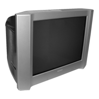
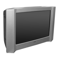
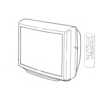
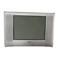
Sony Trinitron KV-SW212M50 User Manual

Sony Trinitron KV-SW212M50
90 pages
To Next Page IconTo Next Page
Page #1 background imageLoading...
Page #1 background image
TRINITRON
®
COLOR TV
SERVICE MANUAL
BX1S
CHASSIS
MODEL COMMANDER DEST. CHASSIS NO.
KV-SW212M50 RM-GA002 GE SCC-V44G-A
KV-SW212M50 RM-GA002 Malaysia SCC-V37Q-A
KV-SW212M81 RM-GA002 Middle East SCC-V40T-A
KV-SW212M81 RM-GA002 Russia SCC-V13X-A
KV-SW212M83 RM-GA002 India SCC-V45P-A
KV-SW212M83 RM-GA002 Saudi Arabia SCC-V26Y-A
KV-SW212M83/H RM-GA002 Saudi Arabia SCC-V64A-A
KV-SW212N60 RM-GA002 Philippines SCC-V41N-A
KV-SW212P50 RM-GA002 E SCC-V21Y-A
MODEL COMMANDER DEST. CHASSIS NO.
RM-GA002
(Except KV-SW212M83/M83/H) (KV-SW212M83/M83/H)
www.DataSheet4U.net

Table of Contents

Question and Answer IconNeed help?

Do you have a question about the Sony Trinitron KV-SW212M50 and is the answer not in the manual?

Sony Trinitron KV-SW212M50 Specifications

General IconGeneral
BrandSony
ModelTrinitron KV-SW212M50
CategoryTV
LanguageEnglish

Summary

SERVICE MANUAL BX1S CHASSIS

SELF DIAGNOSTIC FUNCTION

1. DIAGNOSTIC TEST INDICATORS

Explains STANDBY indicator flashes and their meaning for error diagnosis.

SECTION 2 SET-UP ADJUSTMENTS

2-2. CONVERGENCE ADJUSTMENT

Steps for adjusting color convergence on the screen.

2-3. FOCUS ADJUSTMENT

How to adjust the focus for a sharp picture.

SECTION 3 CIRCUIT ADJUSTMENTS

3-1. ADJUSTMENTS WITH COMMANDER

Instructions for performing adjustments using the remote commander.

3-2. ADJUSTMENT METHOD

General method for making adjustments using the remote commander.

Adjustment Item Table

ITEM INFORMATION

3-3. PICTURE QUALITY ADJUSTMENT

3-3-1. P MAX/CONTRAST ADJUSTMENT

Procedure for adjusting P MAX and Contrast levels.

3-3-2. SUB COLOR ADJUSTMENT

Steps for adjusting sub-color settings.

3-4. GEOMETRY ADJUSTMENT

SECTION 4 DIAGRAMS

4-1. BLOCK DIAGRAM

Overall block diagram of the TV's system architecture.

4-3-1. A Board - (Block 001) PROCESSOR

4-3-2. A Board - (Block 002) AUDIO

4-3-3. A Board - (Block 003) POWER SUPPLY

4-3-8. C Board Schematic Diagram

4-3-9. J Board Schematic Diagram

4-4. VOLTAGE MEASUREMENT AND WAVEFORMS

C BOARD VOLTAGE LIST AND WAVEFORMS

4-5. PRINTED WIRING BOARDS

C [VIDEO AMP] - C Board -

J [3D] - J Board -

SECTION 5 EXPLODED VIEWS

SECTION 6 ELECTRICAL PARTS LIST

4-3-5. A Board - (Block 005) TUNER

Related product manuals