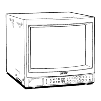
Location and Function of Parts and Controls
[j]] DIGITAL RGB connector (9-pin)
Connect with a microcomputer having a digital (lTL level)
RGB video output.
To monitor the input signal fed through this connector,
press the RGB button and keep the ANALOG/DIGITAL
(EXT SYNC) button released.
-
For connection, be sure to use an optional SMF-520
connecting cable.
[IT] H CENT (horizontal centering) control
When a digital R/G/B signal is monitored, turn to center
the picture if it is decentered.
[!1] EXT SYNC (external sync) connectors (BNC type)
IN: Connect to the output of a sync generator.
To monitor the sync signal fed through this connector,
depress the ANALOG/DIGITAL (EXT SYNC) button.
OUT: Loop-through output of the SYNC IN connector.
Connect to the SYNC input of a video camera.
When the cable is connected to this connector, the
75-ohms termination of the input is released, and the
signal input to the IN connector is output from this
connector.
[li]ANALOG RGB connectors (BNCtype)
R/G/B IN: Connect to the analog R/G/B outputs of a
video camera.
To monitor a signal fed"through these connectors, press
the RGB button and depress the ANALOG/DIGITAL (EXT
SYNC) button.
R/G/B OUT: Loop-through outputs of the R/G/B IN
connectors. Connect to the analog R/G/B inputs of a
video camera.
When the cable is connected to these connectors, the
75-ohms termination of the input is released, and the
signal input to the R/G/B OUT connector is output from
these connectors.
[HJ ANALOG RGB IN connectors (BNC type)
R/G/B IN: Connect to the analog R/G/B outputs of a
video camera.
SYNC IN: Connect to the SYNC output of a video
camera.
12
 Loading...