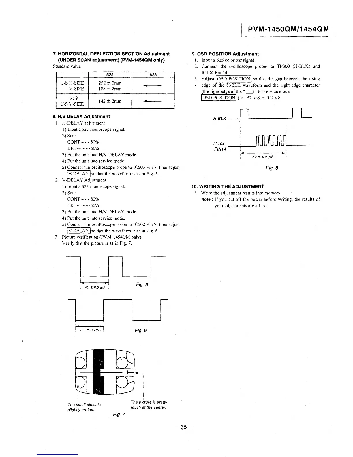
7. HORIZONTAL DEFLECTION SECTION Adjustment
(UNDER SCAN adjustment) (PVM-1454QM only)
Standard value
525
U/S H-SIZE
252 ± 2mm
V-SIZE
188 ± 2mm
16: 9
142 ± 2mm
U/S V-SIZE
8. HN DELAY Adjustment
I. H-DELA Y adjustment
I) Input a 525 monoscope signal.
2) Set:
CONr ...... 80%
BRT·········50%
3) Put the unit into H/V DELAY mode.
4) Put the unit into service mode.
625
5) Connect the oscilloscope probe to JC503 Pin 7, then adjust
I H DELAY! so that the waveform is as in Fig. 5.
2. V-DELA Y Adjustment
I) Input a 525 monoscope signal.
2) Set:
CONT······ 80%
BRT·········50%
3) Put the unit into H/V DELAY mode.
4) Put the unit into service mode.
5) Connect the oscilloscope probe to IC502 Pin 7, then adjust
IV DELAY j so that the waveform is as in Fig. 6.
3. Picture verification (PVM-1454QM only)
Verify that the picture is as in Fig. 7.
41 ±0.5µ5
l
8.0 ± 0.2mS :
The small circle is
slightly broken.
Fig. 7
Fig. 5
I
Fig. 6
The picture is pretty
much at the center.
PVM-1450QM/1454QN
9. OSD POSITION Adjustment
1. Input a 525 color bar signal.
2. Connect the oscilloscope probes to TP300 (H-BLK) and
IC104 Pin 14.
3. Adjust ~, O_S_D_P_O_S_IT_I_O_N~I so that the gap between the rising
edge of the H-BLK waveform and the right edge character
(the right edge of the "D" for service mode
IOSD POSITION!) is: 57 µS + 0.2 µS
H-BLK
'i,1:,44 ------~'
57± 0.2 µS
Fig. 8
10. WRITING THE ADJUSTMENT
I. Write the adjustment results into memory.
Note: If you cut off the power before writing, the results of
your adjustments are all lost.
- 35 -






 To Next Page