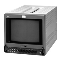
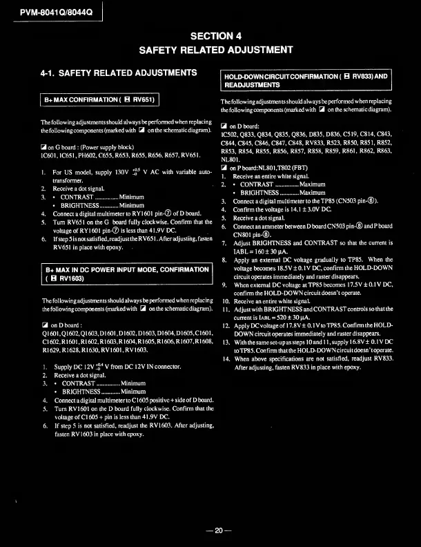
PVM-8041Q/8044Q
SECTION
4
SAFETY
RELATED
ADJUSTMENT
4-1.
SAFETY
RELATED
ADJUSTMENTS
|
B+
MAX
CONFIRMATION
(
B
RV651)~|
The
following
adjustments
should
always
be
performed
when
replacing
thefollowingcomponents
(marked
with
3
on
the
schematic
diagram).
3
on
G
board
:
(Power
supply
block)
IC601,
IC651,
PH602,
C655,
R653,
R655,
R656.
R657,
RV651.
1.
For
US
model,
supply
130V
!jj'
5
v
AC
with
variable
auto¬
transformer.
2.
Receive
a
dot
signal.
3.
•
CONTRAST.Minimum
•
BRIGHTNESS.Minimum
4.
Connect
a
digital
multimeter
to
RY1601
pin-®
of
D
board.
5.
Turn
RV651
on
the
G
board
fully
clockwise.
Confirm
that
the
voltage
of
RY1601
pin-®
is
less
than
41.9V
DC.
6.
If
step
5
is
not
satisfied,
readjust
theRV651.
After
adjusting,
fasten
RV651
in
place
with
epoxy.
B+
MAX
IN
DC
POWER
INPUT
MODE,
CONFIRMATION
(
B
RV1603)
The
following
adjustments
should
always
be
performed
when
replacing
thefollowingcomponents(markedwith
3
on
the
schematic
diagram).
3
on
D
board
:
Q1601,Q1602,Q1603,D1601,D1602,
D1603,D1604,D1605,C1601,
C1602,R1601,R1602,R1603,R1604,R1605,R1606,R1607,R1608,
R1629,
R1628,
R1630,
R
V1601,
R
V1603.
HOLD-DOWNCIRCUITCONFIRMATION(
B
RV833)AND
READJUSTMENTS
The
following
adjustments
should
always
be
performed
when
replacing
thefollowingcomponents
(marked
with
3
on
the
schematic
diagram).
3
on
D
board:
1C502,
Q833,
Q834,
Q835,
Q836,
D835,
D836,
C519,
C814,
C843,
C844,
C845,
C846,
C847,
C848,
RV833,
R523,
R850,
R851,
R852,
R853,
R854,
R855,
R856,
R857,
R858,
R859,
R861,
R862,
R863,
NL801.
3
on
P
board:NL801
,T802
(FBT)
1.
Receive
an
entire
white
signal.
2.
•
CONTRAST.Maximum
•
BRIGHTNESS.Maximum
3.
Connect
a
digital
multimeter
to
the
TP85
(CN503
pin-®).
4.
Confirm
the
voltage
is
14.1
±
3.0V
DC.
5.
Receive
a
dot
signal.
6.
Connect
an
ammeter
between
D
board
CN503
pin-®
and
P
board
CN801
pin-®.
7.
Adjust
BRIGHTNESS
and
CONTRAST
so
that
the
current
is
IABL=
160±30|iA.
8.
Apply
an
external
DC
voltage
gradually
to
TP85.
When
the
voltage
becomes
18.5V
±
0.1V
DC,
confirm
the
HOLD-DOWN
circuit
operates
immediately
and
raster
disappears.
9.
When
external
DC
voltage
at
TP85
becomes
17.5V
±
0.1
V
DC,
confirm
the
HOLD-DOWN
circuit
doesn’t
operate.
10.
Receive
an
entire
white
signal.
11.
Adjustwith
BRIGHTNESS
and
CONTRAST
controls
so
that
the
current
is
Iabl
=
520
±
30
|iA.
12.
Apply
DC
voltage
of
17.8V
±
0.1V
to
TP85.
Confirm
the
HOLD¬
DOWN
circuit
operates
immediately
and
raster
disappears.
13.
With
the
same
set-up
as
steps
10
and
11,
supply
16.8
V
±
0.1V
DC
to
TP85.
Confirm
that
the
HOLD-DOWN
circuit
doesn
’
t
operate.
14.
When
above
specifications
are
not
satisfied,
readjust
RV833.
After
adjusting,
fasten
RV833
in
place
with
epoxy.
1.
Supply
DC
12V
* 1 2 3
4
5 6
V
from
DC
12V
IN
connector.
2.
Receive
a
dot
signal.
3.
•
CONTRAST.....Minimum
•
BRIGHTNESS.Minimum
4.
Connect
a
digital
multimeter
to
C1605
positive
+
side
of
D
board.
5.
Turn
RV1601
on
the
D
board
fully
clockwise.
Confirm
that
the
voltage
of
C1605
+
pin
is
less
than
41.9V
DC.
6.
If
step
5
is
not
satisfied,
readjust
the
RV1603.
After
adjusting,
fasten
RV1603
in
place
with
epoxy.
—
20
—