Do you have a question about the Sony UP-895MD and is the answer not in the manual?
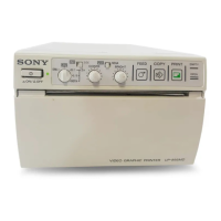
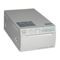
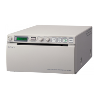
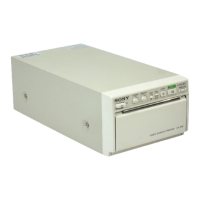
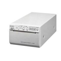
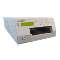
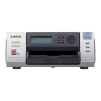
General introduction to the UP-895 printer, its features, and capabilities.
Instructions for connecting, setting up the printer, and loading paper.
Guidelines for storing unused paper and printouts to maintain quality.
Details on loading paper, making printouts, copying, and managing print jobs.
How to copy printouts and select printing direction and image size.
How to adjust contrast and brightness using front panel controls and DIP switches.
Using remote control unit or foot switch for printer operation.
Important safety measures for operating the printer, including installation and carriage safety.
Instructions for cleaning the printer's cabinet and thermal head.
Details on power, dimensions, thermal head, connectors, and supplied accessories.
Pin assignment details for the remote connector.
Diagnostic flowcharts for common issues like faulty prints, paper jams, or sensor errors.
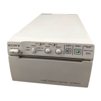
Identifies and explains the function of front panel buttons, switches, and lamps.
Details on the function of sharpness, gamma, paper type, and smoothing switches.
Diagram showing board locations and instructions for removing the top cover.
Step-by-step procedures for removing key components like the mechanical block and boards.
Guidance on tightening screws and installing the fan motor during reassembly.
Procedures for adjusting AGC and video signal levels for optimal performance.
Steps to adjust brightness, contrast, and head voltage for accurate print output.
Procedure to reset the printer's internal print count history.
Overview of printer circuits, including video signal processing and A/D-D/A conversion.
Details on clock generation, memory management, and thermal head control circuits.
How the system control IC manages keys, switches, motors, sensors, and other printer operations.
In-depth explanation of the thermal head's structure, basic operation, stair generation, and corrections.
Diagnostic flowcharts for common issues like faulty prints, paper jams, or sensor errors.
Procedures for printing test patterns, checking head/feed operation, and managing print history.
Detailed pin configurations for diodes, LEDs, transistors, ICs, and other semiconductors.
Guidelines for selecting and using spare parts, including warnings and standardization notes.
Diagrams illustrating the breakdown of major printer assemblies for part identification.
Lists of electronic components for each circuit board (KY-454, MA-99, SU-52, SE-531, SE-532).
List of frame parts, packing materials, and supplied accessories for the printer.
Schematic diagrams illustrating the functional blocks and interconnections of the printer system.
Detailed circuit diagrams for the printer's main boards and assemblies.
Physical component layout diagrams for various circuit boards.
Methods for measuring AC leakage current from exposed metal parts.