3-1
UP-895/(E)
[Equipment Required]
. Oscilloscope
. Digital voltmeter
. 10 steps signal generator
Tektronix 1410 or equivalents (For NTSC signal)
Tektronix 1411 or equivalents (For PAL signal)
3-1. AGC Adjustment
Section 3
Electrical Alignment
Machine condition for adjustment
. Input signal: 10 steps signal
. No monitor is connected.
. Set rear panel DIP switch 9 to up.
(AGC-ON)
Procedure
1. Input a 10 steps signal and set DIP
switch != to DOWN. Adjust RV3 (AGC
REF) so that Vs is 700 mV.
2. Set DIP switch != to UP and adjust RV2
(AGC GAIN) so that Vs is 630 mV.
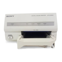
Specification
TP5 (AMP IN)/MA-99 (C-3) Output waveform
. Adjust so that Vs is 700 mV when AGC is ON
and 75 Z terminator is on.
. Adjust so that Vs is 630 mV when AGC is ON
and 75 Z terminator is off.
Vs
Adjustments
AGC REF adjustment
1RV3/MA-99 (C-2)
AGC GAIN adjustment
1RV2/MA-99 (C-2)
1RV3
1RV2
TP5
MA-99
3-2. Video Level Adjustment
Machine condition for adjustment
. Input signal: 10 steps signal
. In case, monitor is not connected, set DIP
switch != on the rear panel to ON, if
connected, set to OFF.
. Adjust RV4 (AGC OFF CONT) using 10
steps signal input.
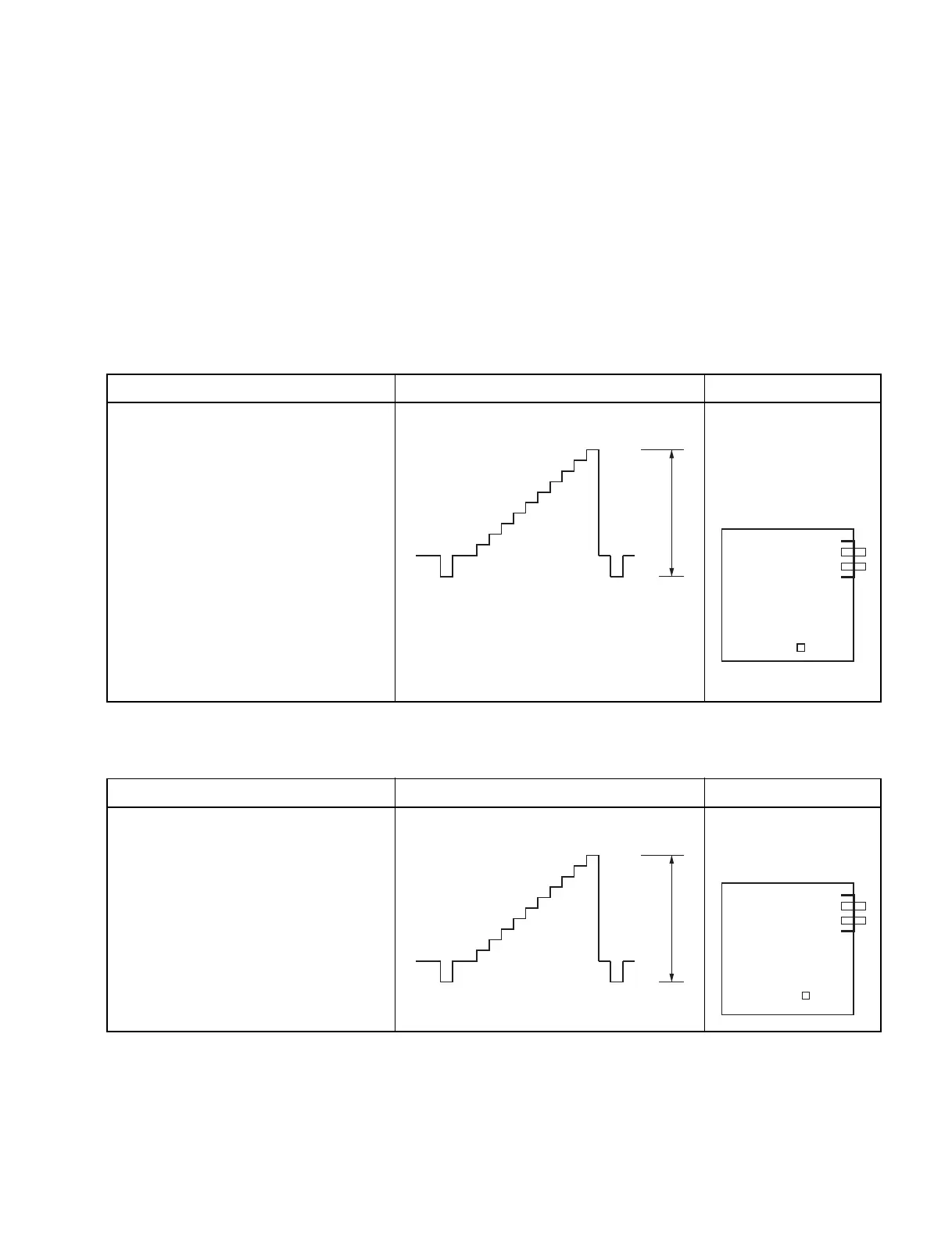
Specification
TP5 (AMP IN)/MA-99 (C-3) Output waveform
Adjust so that video signal level is 1.0 V.
Adjustments
AGC OFF CONT
adjustment
1RV4/MA-99 (C-2)
1.0 V
MA-99
TP5
1RV4
 Loading...