VPCEB Series Optical Disk Drive
Replacement Instructions
P/N 989201349 Rev. C 2/3
Using the enclosed magnetic
screwdriver, remove the two (2) screws
securing the ODD Bay. Put aside the
ODD Bay screws to re-secure the
ODD Bay later in the procedure.
Insert your fingers in the space
between the ODD and the unit
.
Gently
pull towards the left to remove the
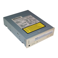
ODD.
Carefully remove the ODD
assembly from the unit.
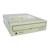
Step 7. Identify the four (4) side screws
that secure the ODD brackets to the
ODD.
Remove the screws & brackets.
Put the ODD Brackets and screws
aside for transfer to the new ODD.
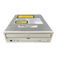
Arrange the brackets &
screws as shown above. Set the old
ODD aside.
Bezel Tab
ODD Tab Hole
Step 11. Align the tabs on the bezel
with the tab holes located on the
ODD. Carefully press the bezel into
place.
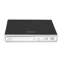
Step 10. Take the new ODD and bezel
provided in the CRU kit and prepare for
assembly.
Identify tabs on the bezel and
tab holes located on the ODD.
R
B