EasyManua.ls Logo

Sony WM-150 User Manual

Sony WM-150
14 pages
To Next Page IconTo Next Page
Page #1 background imageLoading...
Page #1 background image
AEP
Model
UK
Model
E
Mode!
Dolby
noise
reduction
manufactured
under
license
from
Dolby
Laboratories
Licensing
Corporation.
“DOLBY”
and
the
double-D
symbo!
DJ
are
trademarks
of
Dolby
Laboratories
Licensing
Corporation.
SPECIFICATIONS
Frequency
response
(DOLBY
NR
OFF)
20-18,000
Hz
(with
the
TAPE
selector
set
to
NORM
or
CrO,/METAL)
Model
Name
Using
Similar
Mechanism
New
Mechanism
Tape
Transport
Mechanism
Type
Output
Earphones
(stereo
minijack)
load
impedance
8-300
Power
output
SmW+5mW
at
DC
operation
|
TABLE
OF
CONTE
NTS
(at
10%
harmonic
distortion)
loard
impedance
16
Q
;
;
Power
requirements
1.5V
OC
Section
.
Title
Page
Rechargeabie
battery
.
One
R6
(size
AA)
battery
DC
IN
1.5V
jack
accepts
(Using
battery
case):
Specifications
.
Sony
AC-D1M
power
adaptor
(optional)
Sony
EBP-10
battery
case
(Optional)
for
use
with
two
R6
(size
AA)
batteries
Sony
DCC-70
car
battery
cord
(optional)
for
use
SECTION
1.
SERVICING
NOTE
PROBA
aS
Be
with
12V
car
battéry
.
Battery
life
(DOLBY
NR
OFF)
SECTION
2.
GENERAL
Tape
playback
; :
Location
and
Function
of
Controls
........
3
Approx.
4
hours
Approx.
7.5
hours
Rechargeable
NC-6WM
(fully
charged)
Sony
alkaline
battery
AM3
(N)
Sony
battery
SUM-3
(NS)
Approx.
3
hours
Rechargeable
NC-6WM
+
Sony
AM3
(N)
Approx.
11
hours
For
maximum
performance
we
recommend
the
use
of
alkaline
batteries.
SECTION
3.
ADJUSTMENTS
3-1.
Mechanical
Adjustments.
.
Ooi
Bt
He
Se
eae.
os
i
Se
3-2.
Electrical
Adjustments.
.
BPs
oa),
tach
Scag.
ee,
1
Dimensions
Approx.
106.4
70.1xx22.1mm
(w/hid)
not
incl.
projecting
parts
and
controls
Approx.
108*74.4x226mm
(w/h/d)
SECTION
4.
DIAGRAMS
incl.
projecting
parts
and
controls
:
Weight
Approx.
185g
incl.
rechargeable
battery,
not
incl.
4-1,
Semiconductor
Lead
Layouts
see
ee
ew
.
6
other
accessories
-2.
Printed
Wiring
Boards.......
7
Accessories
supplied
Battery
case
(1)
Carrying
case
(1)
4-2.
he
6
Bye
ee
Battery
charger
(1)
Rechargeable
battery
(1)
4-3.
Schematic
Diagram
......,.,,...
..
29
Stereo
earphones
(1)
.
AC
plug
adaptor
(1)
(E_
model)
4-4.
IC
Block
Diagram
....
.
oe
ae
See
oS,
SECTION
5.
EXPLODED
VIEWS.
.
.
.
.
i
3
SECTION
6.
ELECTRICAL
PARTS
LIST.
.
..
16
Note:
Use
only
the
recommended
AC
power
adaptor
or
car
battery
cord
manufactured
by
Sony.
Polarity
of
the
plugs
of
other
manufacturers
may
be
different.
i
CASSETTE
PLAYER
SONY.
|
Question and Answer IconNeed help?

Do you have a question about the Sony WM-150 and is the answer not in the manual?

Sony WM-150 Specifications

General IconGeneral
TypeWalkman
BrandSony
ModelWM-150
Tape Speed4.76 cm/s
Power SourceBattery
Battery TypeAA
OutputHeadphones
Wow and Flutter0.15% (WRMS)
Signal-to-Noise Ratio50 dB
Battery2 x AA batteries
Frequency Response40 Hz - 15 kHz

Summary

Specifications

Section 1 Servicing Note

Section 2 General

Location and Function of Controls

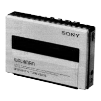
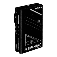
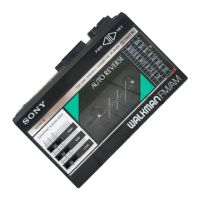
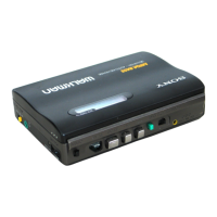
Details the purpose and placement of all external controls on the WM-150 device.

Section 3 Adjustments

3-1. Mechanical Adjustments

Procedures for cleaning, demagnetizing, and adjusting mechanical parts like heads and pinch rollers.

3-2. Electrical Adjustments

Procedures for adjusting tape speed, playback level, and phase using test tapes and meters.

Section 4 Diagrams

4-1. Semiconductor Lead Layouts

Provides pin configuration diagrams for various semiconductors used in the device.

4-2. Printed Wiring Boards

Shows the layout of components and traces on the main and head connection boards.

4-3. Schematic Diagram

Detailed circuit diagram illustrating the electronic components and their interconnections.

4-4. IC Block Diagram

High-level block diagrams showing the internal functions of key integrated circuits.

Section 5 Exploded Views

5-1. General Section

Exploded view of the general assembly and parts for the WM-150 cassette player.

5-2. Mechanism Section-1

Detailed exploded view of the first part of the tape transport mechanism.

5-3. Mechanism Section-2

Detailed exploded view of the second part of the tape transport mechanism.

Section 6 Electrical Parts List

Related product manuals