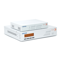
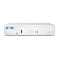
5SD-RED 20 / SD-RED 60
Operating Instructions
Important note: If you accidentally connect one 802.3at and one other 802.3at
or 802.3af device at the same time, power for the device on LAN3 (lower priority)
will be disabled and the connected device will lose power. The PoE LED of this
port will start blinking, indicating a PoE power error, until you remove one of the
devices from the LAN1 or LAN3 port (please also see PoE LED table above).
Adding an optional 3G/4G or Wi-Fi expansion module
Both SD-RED models have an expansion bay at the back allowing you to add
either a Sophos 3G/4G or a Wi-Fi module, which are available from your Sophos
partner.
Both modules are shipped with two antennas (for 3G/4G or 802.11 ac 2x2 Wi-Fi).
The wireless module allows you to connect wireless devices to your local LAN at
the remote site.
The 3G/4G module can be used as an alternative mobile WAN connection.
For installation instructions, please refer to the documentation available at www.
sophos.com/get-started-sd-red.
Connecting devices to the SFP port
Both SD-RED models provide an SFP port which can be used to connect the unit
to the local router/cable modem or other set-top box via fiber or other standard
SFP mini-GBICs (transceivers).
This port is a combo port shared with the WAN1 port. Therefore, you can only use
one of these ports at any time.
If cables are connected to both ports, the SFP port will take precedence.
Using redundant power supplies
Both SD-RED models are shipped with a single power supply, but provide a
connector to add a second redundant power supply, allowing you to keep your
appliance up and running even if one power supply fails.
The power LED for the respective power supply on the front of the device will only
be activated once you have connected a second power supply for the first time,
i.e. it will turn red in case the connected power supply fails or there is no power
supply connected to the second connector at all.
Serial console
You can connect a serial console to the Micro-USB COM port of the SD-RED
devices. You can use, for instance, the HyperTerminal terminal program which
is included with most versions of Microsoft Windows to log on to the appliance
console. Use a Micro-USB to USB-A adapter cable to connect the console to your
SD-RED device.
The required connection settings are:
Ì Bits per second: 115,200
Ì Data bits: 8
Ì Parity: N (none)
Ì Stop bits: 1
Ì Flow Control: N (none)
Access via the serial console is activated by default on ttyS1. The connections
of the appliances and the respective functionality are listed in the chapter
“Operating Elements and Connections.”
 Loading...